Background
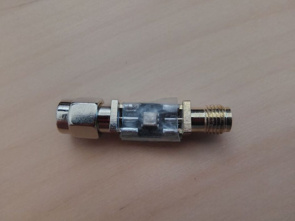
Filters are a hotly contested topic in the realm of Meshtastic and Meshcore. Often for mesh radios, bandpass filters are the specific type of filters of primary interest. The job of these filters is to allow only a set band of frequencies to pass through the filter and attempt to reject frequencies outside of this band. These filters are most often used for situations to help improve the receive capability of a mesh radio, specifically for radios located in a noisy environments. For some applications these filters can also be used to attenuate spurious emissions emanating from the radio when transmitting.
Selection and Performance Criteria
One of the most important attributes to consider when selecting a filter is determining what you are trying to filter out. Filtering out an out of band transmitter from a bit of a distance away from desensing your mesh radio is one task while attempting to reject in band neighboring 900Mhz ISM band interference is a completely different animal and thus requires a more precise and expensive filter, such as a cavity filter with a steep cut off frequency.
It is important to be aware that with most filters you get what you pay for and there is “no free lunch”. In other words don’t expect a $15 dollar filter off of a Amazon or Aliexpress to out perform a $150 cavity filter.
Typical performance criteria of a band pass filter includes close consideration to a few attributes including: center frequency, cut off frequency, pass bandwidth, pass band insertion loss and filter shape.
Insertion Loss: Its worthy the mention that one of the draw backs to using a filter is the added loss that you get with the filter inline. It is not uncommon to see insertion loss measurements for filters to vary from -0.8 to -3dB in the pass band. For those that are not very familiar with RF it is important to realize that a -3dB loss means that the filter is causing half of the RF power in the line to be lost thus filters with values closer to 0dB are more desirable.
Center Frequency: Most often described as the frequency for which the insertion loss is the closest value to 0dB, typically we want the center frequency to be fairly close to our operating frequency.
Cutoff Frequency: The cut off frequency for a bandpass filter is generally two different frequencies defined as the frequencies for which are -3dB lower than the center frequency. In other words if a filter has a center frequency of -0.8dB the cut off frequencies will be the frequencies for which the loss is -3.8dB.
Filter Bandwidth or Passband: Filter bandwidth is essentially the difference between the upper and lower cutoff frequencies. As an example if the cut off frequencies for a filter is 904.05Mhz and 910.80Mhz then the filter bandwidth is 6.75Mhz. Typically the narrower the filter the better, but often sharper filters are more expensive and may have higher insertion loss so significant consideration is required for this trade off.
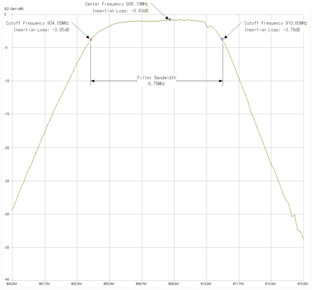
Figure 1. Typical Bandpass Filter Parameters Illustrated
BayMesh BM3 Filter Example Shown
Filter Shape: As the nomenclature suggests different filters may have different shapes when it comes to its RF characteristics. Typically we want the pass band region to be fairly flat however some filters have the characteristic of having multiple “bumps”.
How do I know if I need a band pass filter?
Whether a bandpass filter is needed is a common and difficult question to answer and heavily depends on site and surrounding environment the mesh radio is located. For example a node placed in a rural environment will have a completely different RF experience than a node placed on a high rise in a downtown city, collocated at a site with high powered transmitters.
One quick and easy way to assess if a mesh may benefit from a filter is to measure the noise floor on the radio. Both Meshcore and Meshtastic have added features into their firmware to acquire measurements of the RF noise floor. The lower the noise floor, or further away from 0 the better. As a rough rule of thumb many suggest trying to have a noise floor lower than -100dBm. It is worth mentioning that at the time of this write up the Meshtastic noise floor is currently available through the iOS app and may not yet be available through the Android app. If it is available on the Android app I just haven’t located it yet.
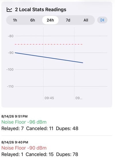
Figure 2. Meshtastic Noise Floor Measurement – Local Stats
If a mesh radio is being installed in an area where it can be accessed I highly recommend doing some A-B testing, or testing the radio performance before installing a filter and after the filter is installed. Meshtastic users have performed this testing by, at random, seeing for each situation how many nodes pop up on their node list after different durations of time such has 30min, 1hr and 3hrs. Due to varying conditions it would be recommended to perform this testing at a few different random days and times of the day.
For nodes that will not be easily accessible such as a tower node or a building with extremely limited access I highly recommend performing a site survey of the noise floor using a node mounted onto a drone and deployed at the intended height.
For more complex measurements and to get a better pictures of in band and adjacent band neighboring transmitters a spectrum analyzer such as a TinySA or professional spectrum analyzer can be used.
As a rough rule of thumb, if you are installing into a tall location in a downtown area you will likely need a cavity filter with a sharp cutoff frequency. For a home node you maybe ok without any filtering and the added loss from the filter may not be worth it. More rural installations really depend on where the mesh radio is being installed, if the site is not a high RF site one maybe able to get away without using an expensive cavity filter and maybe able to get away with a more inexpensive filter or no filter at all.
Testing a Band Pass Filter
Testing a band pass filter is not all too terribly difficult, the main tool you used is a vector network analyzer (VNA). For most work being done with Meshtastic or Meshcore a simple TinyVNA would suffice. I will include additional detail on these measurements in a future topic.
Next Post – Taking the Measurements →
Note: Permission has been expressly granted for this topic write up to be reposted on www.eastsidemesh.com