Background
The goal of this post is to assist others with demonstrating how measure typical characteristics of a Meshtastic / Meshcore band pass filter.
Equipment
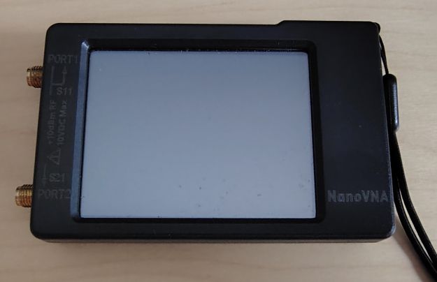
A few very basic pieces of test items are required to measure the characteristics for a band pass filter. This includes a VNA, for the sake of this post Ill be using a NanoVNA as an example. If you do not already have one a standard NanoVNA can be purchased for just under $50 USD. I highly recommend spending the extra money for the option with a larger screen as the standard 2.8in screen quite compact is can be a bit difficult to see and navigate using the touch screen.
If you are planning to use your NanoVNA at work bench with a computer I highly recommend getting NanoVNA Saver. This free software allows you to connect your NanoVNA to your computer allows you control the VNA, see and create the plots all from the convenience of your computer.
I should also mention that there are alternative firmware available for the NanoVNA that provide for additional measurement functions. I personally have not yet explored these alternatives so I can not comment too much on them.
In addition to the NanoVNA be sure you have the calibration standards, some short RF test leads and any required RF adapters. In summary:
- VNA
- Calibration Standards
- Test leads and adapters
- VNA to computer interface software [Optional]
NanoVNA Calibration – Methodology
Prior to taking any measurements with a VNA it is best to set the test frequency range prior to calibrating the unit and to utilize the actual test leads and adapters that you anticipate using for the measurements during the calibration process.
There are a few reasons for these recommendations. For the measurement that your VNA acquires, it continuously samples around 101 frequencies that are between the frequency range you have specified. Thus if you calibrate the unit while the measurements are setup for 1-30Mhz but you intend to take measurements between 900-950Mhz you have not correctly calibrated the unit, the calibration is only effective for between 1-30Mhz.
A good reason for including your test leads and adapters as much within reason is when you calibrate the unit with these components the calibration procedure will calibrate out the loss of your test leads giving you a much more accurate measurement of the unit under test (UUT).
NanoVNA Calibration – Steps
Based on the inital settings of your NanoVNA the following settings may slightly vary from user to user but should be somewhat similar:
Set the mode and measurement format:
DISPLAY > CHANNEL > S21
DISPLAY > FORMAT > [✓]LOGMAG
To Exit the menu BACK > BACK
Set start and stop Frequency:
STIMULUS > START > [900Mhz – For Mesh filter testing]
STIMULUS > STOP > [950Mhz – For Mesh filter testing]
To Exit the menu BACK >
Calibration:
CALIBRATE > CALIBRATE
- Connect the OPEN test adapter to PORT 1 and select OPEN
- Connect the SHORT test adapter to PORT 1 and select SHORT
- Connect the 50ohm test adapter to PORT 1 and select LOAD
- With nothing connected to Port 1 or 2, select ISOLN
- Connect your desired test leads to Port 1 and Port 2, then connect the cables together, as shown in Figure 1. Note: An additional adapter maybe required for this step. Select THRU.
- Select DONE > SAVE 0
- If your calibration steps were correct, with the test leads still connecting Port 1 and Port 2, the plot should show 0.0dB for the entire range. If it does not perform the calibration proceedure again.
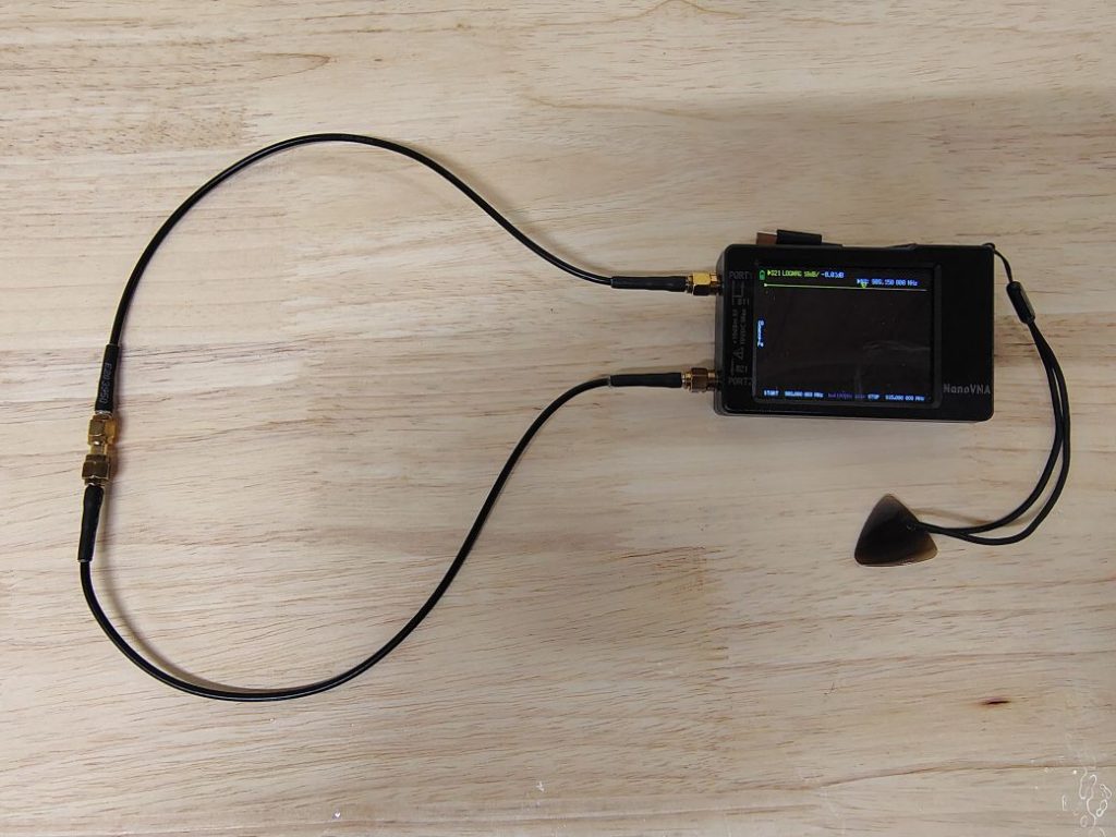
Figure 1. NanoVNA Thru Calibration
Its important to note that the device should be recalibrated often. If your measures are in question, recalibrate!
Unit under test (UUT)
For the sake of this post the unit under test will be the filter that we are planning to test. For this example I will be using a BayMesh BM3 cavity filter.
Test Setup
The test setup for this type of measurement is fairly simple, since we are testing the loss of a filter we will be using both RF ports on the VNA which in the RF field is known as an S₂₁ test. A picture of the test setup is shown in Figure 2, essentially you connect one port of the filter to one of the ports on the VNA and the opposite port of the VNA to the remaining port on the filter. While the filter I am testing specifically has a port labeled IN and OUT, which port connects to which VNA lead for this specific filter does not matter.
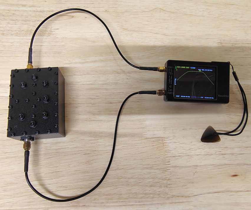
Figure 2. Typical NanoVNA Filter Test Setup
NanoVNA Measurement
Now that we calibrated the VNA are already in LOGMAG measurement mode we can connect our unit under test as shown in Figure 2 and acquire our measurements.See my previous post Meshtastic / Meshcore – Bandpass Filter – Characteristics for details on typical band pass filter attributes. It is often helpful to enable and use the markers to help find specific values.
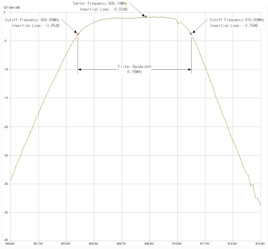
If your band pass filter is function as it should it should look similar to the image shown in Figure 2. I am also including a screen shot of the filter from NanoVNA Saver from my previous post with the included filter characteristics indicated. Note: Different filters will likely have different values for each of these characteristics.
In the next post we will cover a head to head comparison of some commercially available 900Mhz ISM band filters for use with Meshtastic and MeshCore.
Note: Permission has been expressly granted for this topic write up to be reposted on www.eastsidemesh.com