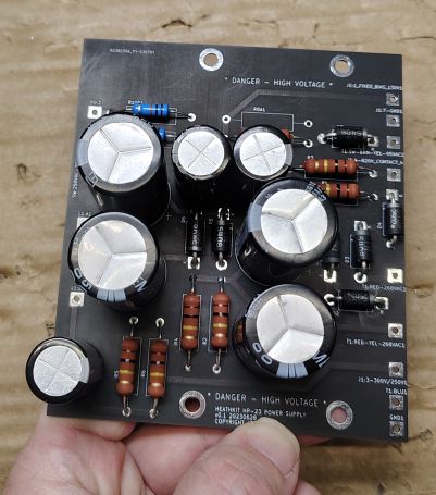
For my original HP-23A refurbishment project I decided to develop my own custom circuit board. It is common for prototype circuit board orders to have small minimum order, however for most fabrication houses in China, even though they force you to have a minimum order the price is still extremely economical and the boards arrive pretty quick. From my past rebuild project I had spare boards to use so I figured why not use one for this rebuild. Most of the components are readily available though most of the larger name electronic part distributors such as Mouser or Digi-key.
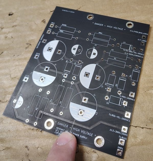
Some of the main features of the board include the fact that it eliminates most of the component point to point wiring. This board also allows the the entire circuit board assembly to tuck into the bottom side of the power supply. One of the trade offs to this particular design is it does require a circuit breaker with a slightly different form and fit, while I was in the process I also replaced the toggle switch with a screw terminal style. In the event future troubleshooting was required I tried to keep the reference designators identical to that of the original Heathkit schematic.
Below is a copy of the schematic and bill of materials that were used for this board. A link to the full sized schematic can be found here. Note: I will include additional schematics in the post that follows and covers wiring. From a quick look you will notice that some of the component values slightly differ from the original schematic. R6 for example only seemed to appear on the schematic for the HP-23C models. Some of this is variation allows for more common readily available part values. Some of the resistor and diode values have been sized for a higher power dissipation rating. Many have reported that Heathkit had a tendency to utilize parts that were on the boarder line of being undersized.

Table 1. Bill of Materials
| Item Number | Reference Designator | Component Type | Part Number (Value) | Quantity | Notes |
|---|---|---|---|---|---|
| 1 | D1-D7 | Diode | 1N5408 | 7 | |
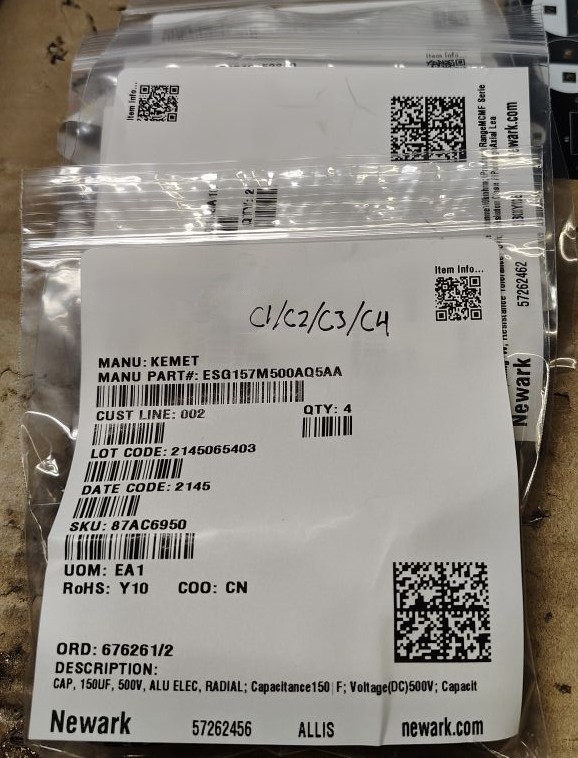
| 2 | C1-C4 | Capacitor | ESG157M500AQ5AA (150uF 500V) | 4 | |
| 3 | C5-C7 | Capacitor | EEUEE2W470 (47uF 450V) | 3 | |
| 4 | L1 | Inductor/Choke | See note 6H | 1 | Reused existing inductor/choke |
| 5 | R1-R6 | Resistor | RR03J100KTB (100kΩ, 3W) | 6 | Metal film used R6 only used for HP-23C models |
| 6 | R7 | Resistor | RR03J1K0TB (1kΩ, 3W) | 1 | Metal film used |
| 7 | R8A1 | Resistor | RR03J27KTB (27kΩ, 3W) | 1 | Metal film used, present for fixed bias only |
| 8 | R8B1 | Resistor | MCMF01WJJ0103A10 (10kΩ, 1W) | 1 | Metal film used, present for adjustable bias only |
| 9 | R9 | Potentiometer | See note (10kΩ) | 1 | Reused existing potentiometer, used for adj bias |
| 10 | R10B1 | Resistor | MCMF01WJJ0103A10 (10k Ohm, 1W) | 1 | Metal film used, present for adjustable bias only |
Since some of the power supplies include an adjustable potentiometer to change the bias while newer versions utilize a fixed resistor I included an option for the installer to take either path. For situations where the bais is fixed R8A1 gets populated and the R8B1 and R10B1 resistor positions remain unpopulated. For situations where the adjustable bias potentiometer is present R8B1 and R10B1 get populated and the original potentiometer gets wired to the R9:1 and R9:3 locations on the board. Here R8A1 will remains unpopulated.
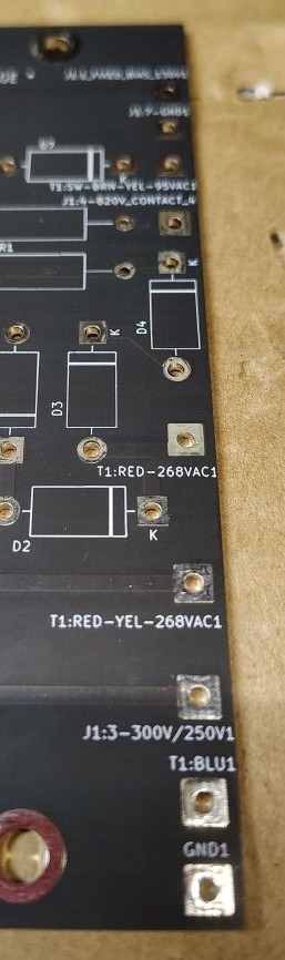
Wire connections between the board and the off board components occurs through plated through holes on the board. Wiring between the chassis mounted components and the circuit board will be covered in the next section.
When starting the circuit board assembly stage of any project I always try to do an inventory of the parts I received and compare them to both the bill of materials and schematic. I find it helpful to label the reference designator (R1,C2, etc) on the bag for each component. This technique can make it quicker to sort through and find a specific part of interest. Sometimes when sourcing parts it can be easy to miss a single component, this is often unfortunate as the shipping costs to ship a single item often cost more than the component itself. Its always a good practice that before submitting and order to do a check of the parts.
Before starting to solder its good to remember that many components such as the electrolytic capacitors and diodes have a polarity that matters, you will want to make sure these components are orientated for the proper polarity when soldering.
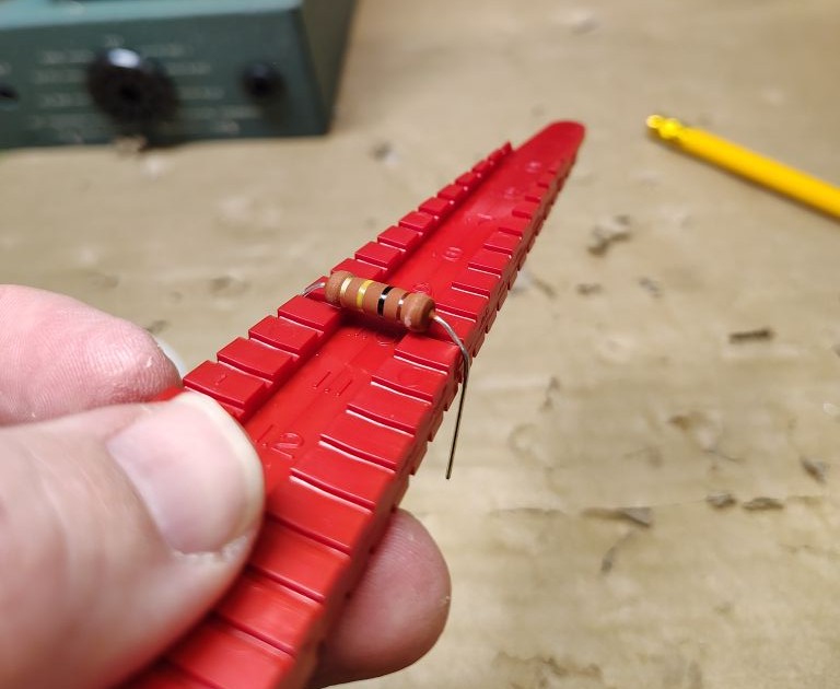
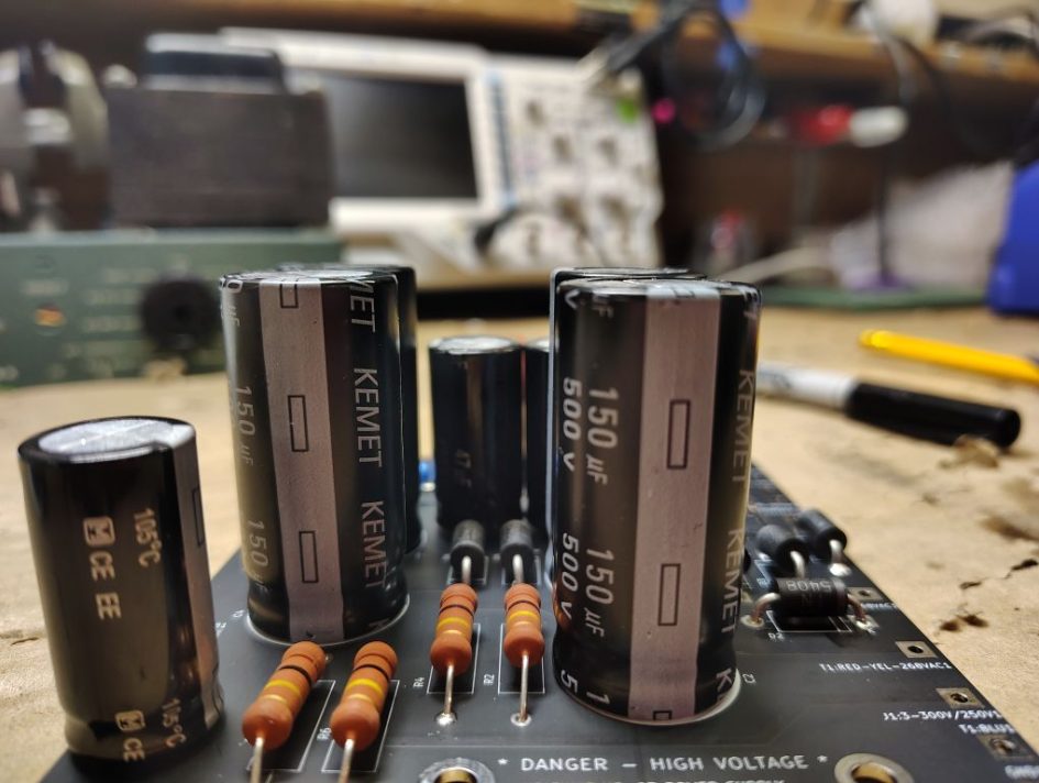
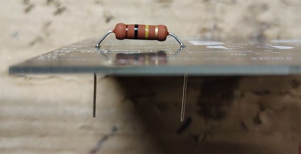
I started off by soldering each of the resistors into place working sequentially through the refence designators. I used a lead forming tool to help make sure that each of my leads were neatly formed. For all of the axial components I shimmed them slightly so that the component bodies were approximately 1/8in off the board. The idea here was that this gives some additional room for air to flow and cool the components and help with long term longevity.
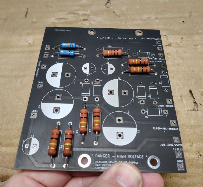
With the resistors all mounted I moved onto soldering each of the diodes into place carefully observing the polarity on the component and the designated polarity on the board.
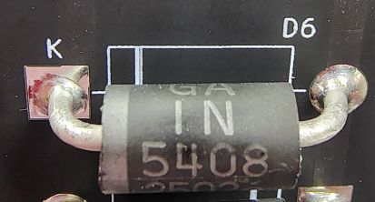
As with the resistors, to support enhanced cooling I shimmed these components approximately 1/8in off the the board when I soldered each of them into place. When the diodes are all installed I take a minute to double check the line indicating the cathode on both the circuit board and diode itself to make sure all of the diodes were installed in the correct orientation.
The next step was to solder in the electrolytic capacitors, as with the diodes polarity for these matters. After I had all seven caps installed I took a minute to check over the polarity as an additional sanity check. With all of the components populated I cleaned the board using Isopropyl Alcohol and then water.
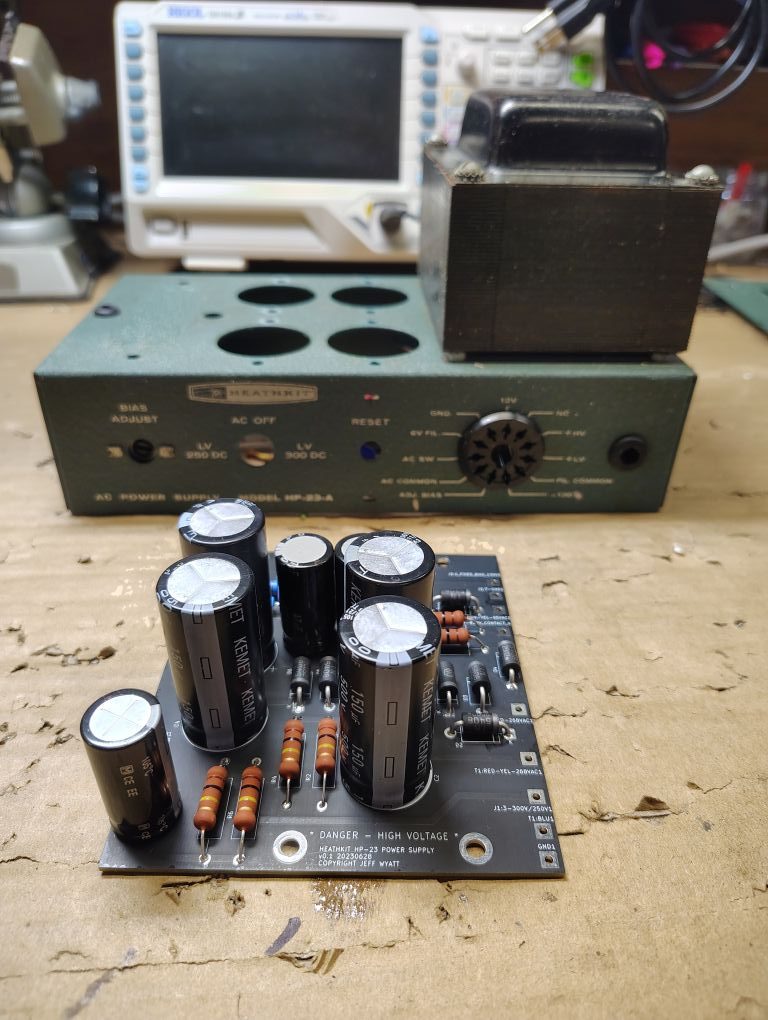
Next step will be to do the wiring for the power supply,
’73!