Why Replace?
It is well known that over time, Electrolytic capacitor dry out and are no longer usable. Some spend time to use a Variac to reform the capacitors, with the HW-101 it is fairly easy to replace these capacitors and its fairly inexpensive for these components, so why not just replace them! It is also a pretty quick process. The most important thing to remember when replacing the capacitor is to make sure that the replacement capacitor goes in with the same polarization as the old capacitor.
While the electrolytic capacitors dry out it is worthwhile to mention that the ceramic disk capacitors, which are plentiful on the rig generally hold up well over time and likely won’t need to be replaced. The only problem I have experienced with the disk capacitors was damage from being a bit overly aggressive during the wash down process.
Electrolytic Capacitor Locations
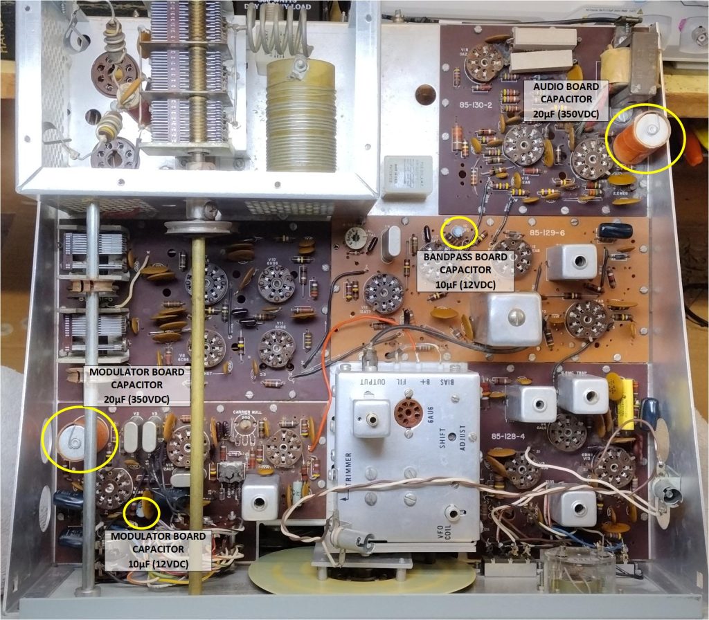
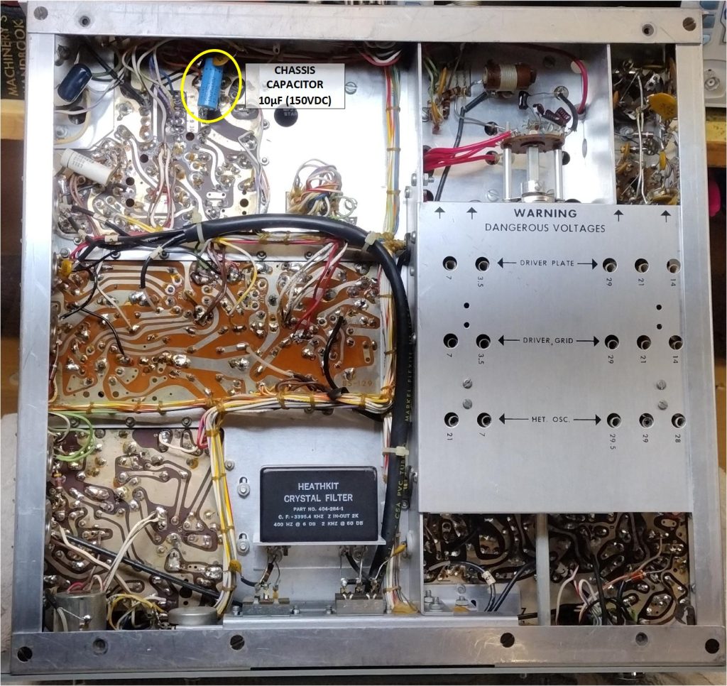
The figures below show the locations of the five electrolytic capacitors to replace.
Replacement Parts
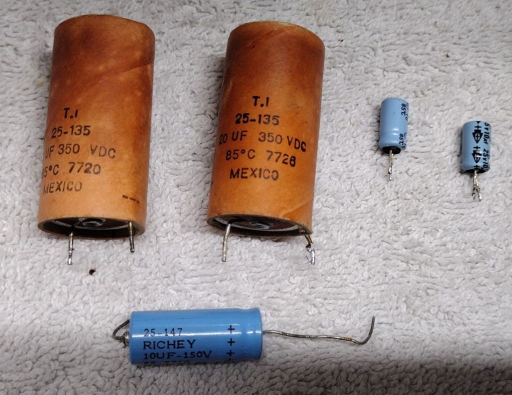
Table 1 shows the values of each of the original electrolytic capacitors along with some replacements that are available from many of the larger electrical component distributors such as Mouser. For availability purposes we replace the 22µF with 20µF capacitors. The old capacitors can also be replaced with new capacitors that have a higher voltage rating without causing any issues.
| Board Location | Original Value | Reference Designator | Heathkit PN | Package | Replacement Value | Part Number | Alternative Part Number |
|---|---|---|---|---|---|---|---|
| Modulator | 10µF (12VDC) | C2 | 25-115 | Radial | 10µF (16VDC) | ESW106M016AC3FA | ECA-1CHG100 |
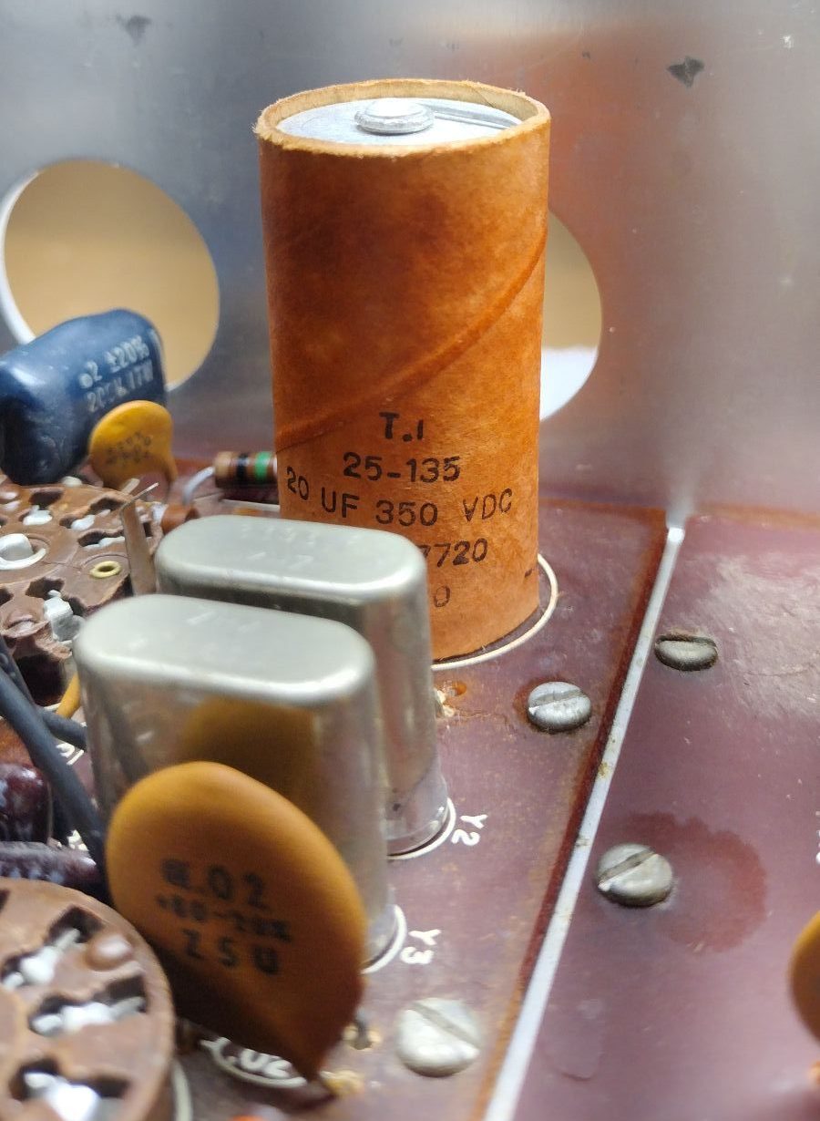
| Modulator | 20µF (350VDC) | C12 | 25-135 | Radial | 22µF (450VDC) | ECA-2WHG220B | EEU-EB2W220S |
| Bandpass | 10µF (12VDC) | C121 | 25-115 | Radial | 10µF (16VDC) | ESW106M016AC3FA | ECA-1CHG100 |
| Audio | 20µF (350VDC) | C304 | 25-135 | Radial | 22µF (450VDC) | ECA-2WHG220B | EEU-EB2W220S |
| Chassis | 10µF (150VDC) | C906 | 25-147 | Axial | 10µF (160VDC) | 30D106M160DC5A |
Table 1. Capacitor Values
To save money on shipping cost I try to place a combined order for replacement resistors at the same as I am purchasing the replacement electrolytic capacitors. If I am planning on rebuilding another radio, in the future, I always try to purchase an extra set of capacitors. For this rig I happened to have a complete set of replacement electrolytic capacitors on hand.
Capacitor Removal and Replacement
For removing the old capacitors you will need a few tools and materials:
- Soldering Iron
- Solder sucker
- Wick
- Flux
- Solder
- Diagonal cutters
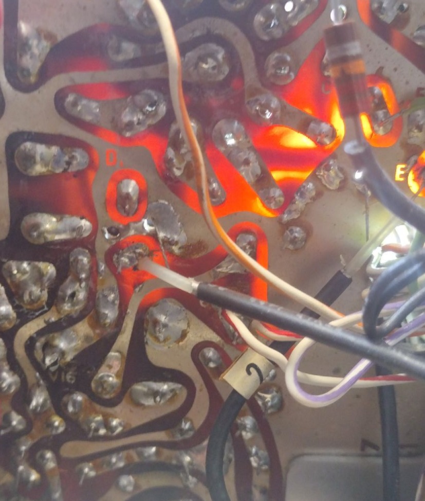
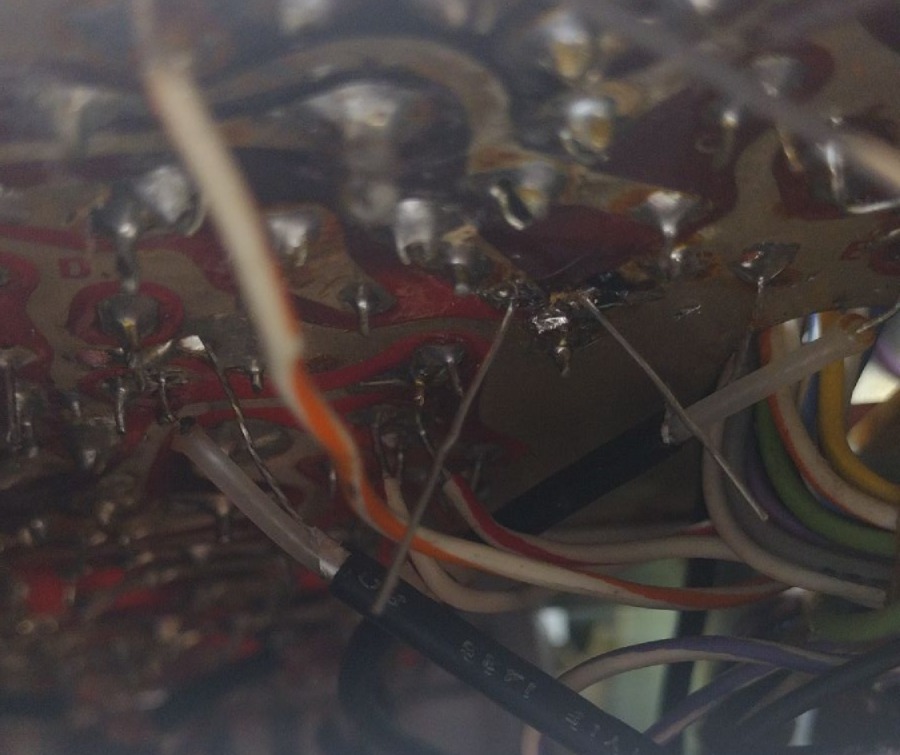
The toughest part of the replacing the capacitors is locating their circuit board pads on the opposite side of the circuit board. One trick that I picked up over time as a handy way of identifying the correct circuit board pads is to shine a flash light through the circuit board. For these boards they surprisingly allow light to pass through them more than you would anticipate.
To remove each capacitor I applied some flux to the solder to be removed, heated the area with my soldering iron and used both a solder sucker and wick. With the old component removed I next applied flux to the area. When loading each capacitor in I doublechecked the orientation of each capacitor to make sure that it is the correct polarization, soldered the component and then cleaned any flux.
The most difficult capacitor to replace on this radio was the 20µF on the Audio circuit board. For this capacitor the negative lead connected to ground was extremely close to where the chassis comes into contact with the circuit board, this made de-soldering and resoldering a bit of a challenge with my Hakko FX888D soldering iron. Anytime I tried to apply heat the heat was sunk into the chassis. To resolve I had to use a higher wattage iron and was able to replace the capacitor.
Overall the capacitor replacement went well and took just a few hours to do. Time to reload the vacuum tubes and power up the radio!
’73!