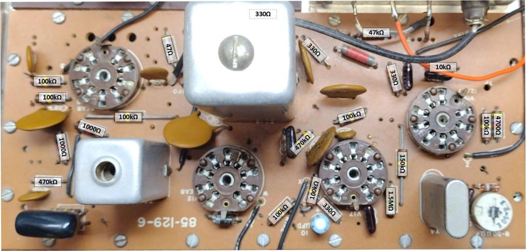
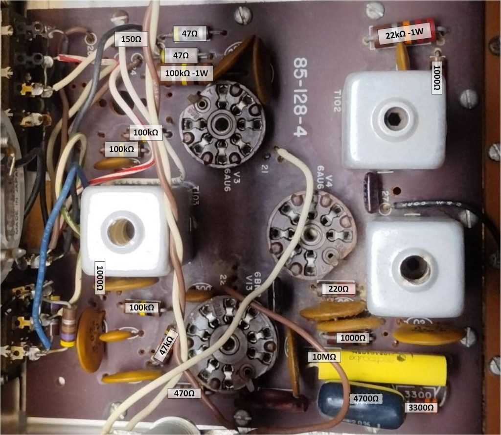
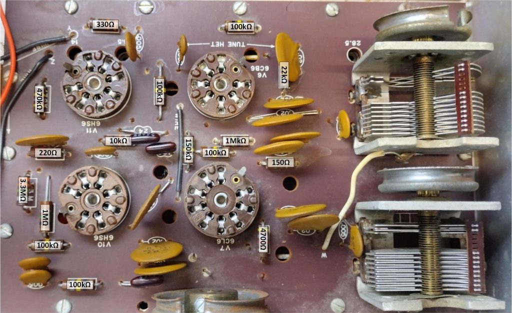
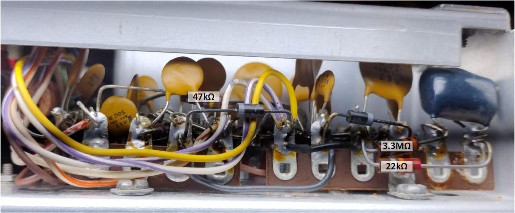
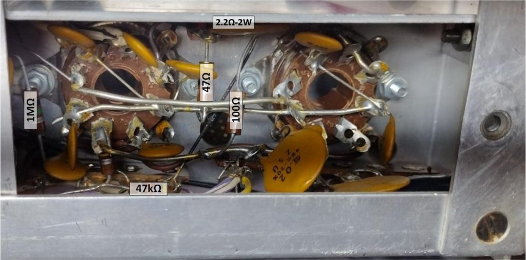
The next step in the refurbishment process is to check all of the resistors to make sure that they are within tolerance. The Heathkit HW-100 series radios use carbon composition resistors that as they age can come out of tolerance. I perform these tests on each board at a time and take a quick moment to check each of the diodes. In this post I am including some images with each of the HW-101 circuit boards with their resistor values super imposed on each image for reference.

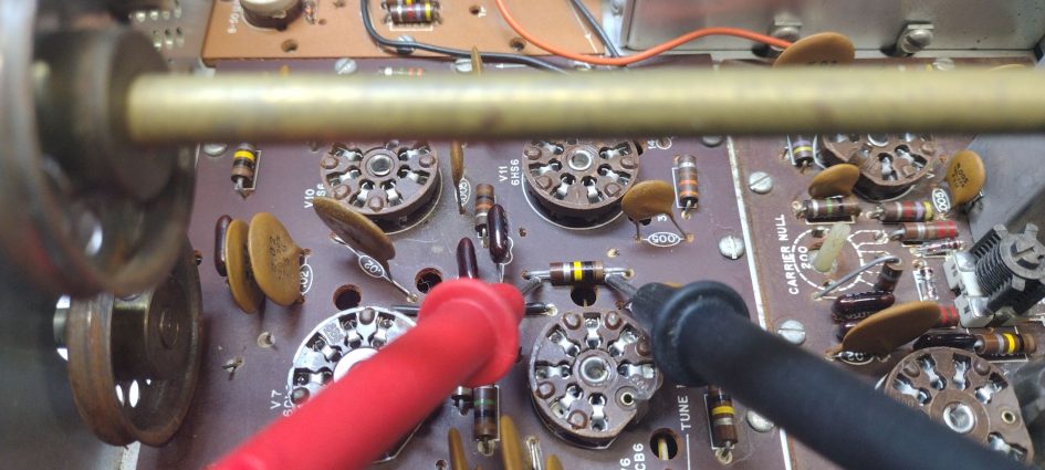
For these tests its most practical to test the resistors in-circuit. Since we are testing these resistors in circuit we can ignore reads that are below tolerance as it could be caused by additional components in parallel with the resistor. I use a pass-fail criterial of being out of tolerance by more than 15% as a indicator that the resistor should get replaced. For resistors that are slightly out of tolerance I use a bit of a judgement call as to whether the resistor needs to be replaced placing a high weight on how difficult it would be to replace the resistor. In cases where the resistor is in a difficult to access location I may just log the resistor as being out of tolerance and see if it causes further issues.
Once I determine the specific resistors values and quantities that need to be replaced I start putting together a shopping list of what I need and start checking his list against my internal parts inventory. When I placing an order for resistors I purchase replacement electrolytic capacitors in the same order for the recapping process that we will discuss in a further post.
Most resistors in the original kit were 1/2-Watt rated with a few exceptions. Carbon composition resistors are not as available as they used to be. When replacing resistors, carbon film type resistors with a 5% tolerance are fairly available and a good choice. While wire wound resistors are commonly available they should be avoided for most RF applications as their the wire windings of Nichrome wire which gives them their desired resistance gives them an undesirable inductive property for RF applications.
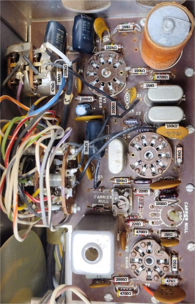
For past Heathkits where I have checked the resistor values I have found that its common to have a half a dozen resistors out of tolerance and in need of replacement, for this rig all of the resistors tested were within tolerance. In the next step we will work on cleaning up the contacts and replacing the old electrolytic capacitors.
’73!