Introduction –
Prior to performing any work on a boat anchor I perform a simple visual inspection to look for obvious issues before we get into the “meat and potatoes” of cleanup. In many cases a through visual inspection should be performed before you even purchase the radio, if you have the ability to do so. This inspection can be very telling of the level of effort you have ahead of yourself if you choose to make the purchase. After performing multiple restorations you get a better idea on the different telltales to look out for.
Restoration Log –
To make sure that these early visual inspection points get addressed at some point in time in the future I start off by creating a simple excel spreadsheet log for the specific radio I am working on. One of the reasons I create this log is that I do not have the opportunity to complete any restoration in a single sitting. Another good reason to log this information is it can help me keep track of each radios specific needs if I am working on more than one radio at a time. In some cases I notice an issue or make a peculiar observation but wont get to the relevant step to address this issue until a few weeks or months later. I use this spreadsheet as a way to track what I have completed for the restoration along with open items that I need to tackle in future stages. Typically I also use this log to track the status and condition of each of the tubes, resistors and a check sheet for the alignment process. The log is nothing fancy but helps to keep me organized and get the job done.
Exterior Inspection –
A few items that I look at when inspecting the exterior of a radio:
- Is the chassis intact and are any pieces missing?
- What is the condition of the paint?
- Does there appear to be any water damage or corrosion?
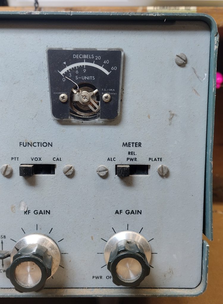
- Are all of the meters intact?
- Are all of the knobs present and in good working order?
- Are the connectors in good condition?
- Are any obvious modifications present?
- Are the required cords included and in good condition? Frayed cords will need to be addressed prior to powering the radio up.
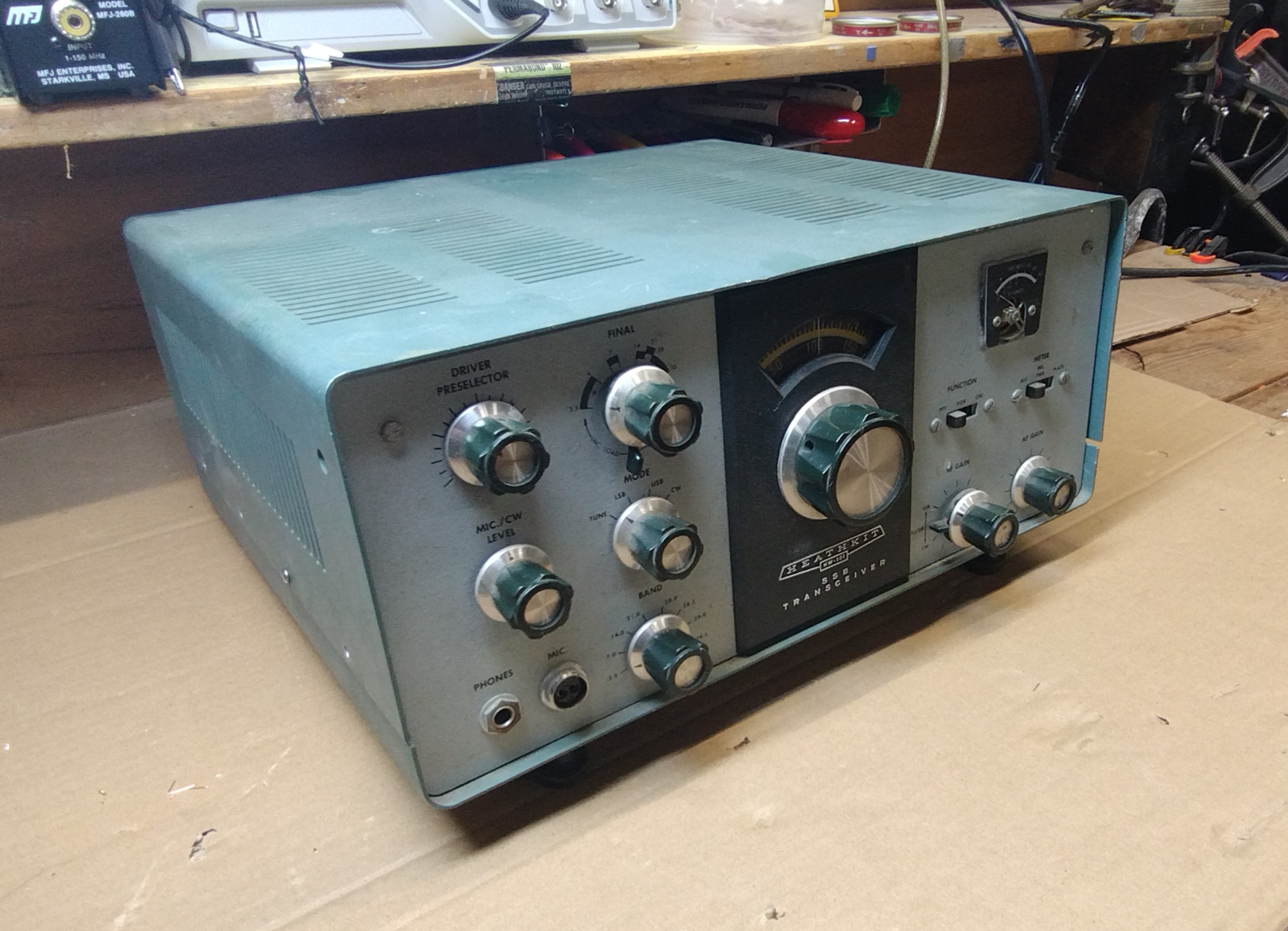
My initial observation of this radio was that the main meter located in the upper right hand corner was damaged, the plastic cover was missing and the needle was bent. Accordingly I have given this radio the nickname of being the needle-bender. Upon a closer inspection of the front panel, it becomes obvious that the radio was unfortunately dropped and not only was the meter damaged but a few minor dents and dings were induced onto the front chassis and the main VFO knob was also slightly bent.
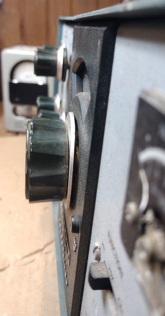
An actuation of all of the knobs shows the VFO deformation allows the knob to still be rotated but some minor rubbing is present. The other knobs on the radio appear to work but as with any un-maintained radio of this vintage will need to be cleaned and re-lubricated.
The radio top cover includes the typical dust and other grime but luckily does not seem to have the odor of nicotine that many radios of this vintage seem to encounter. In many cases, over years of operation with an Amateur having their microphone in one hand and a cigarette in another hand leads to layers of nicotine build up on many of these radios. This build up is often present not only on the outside of the chassis but also on the interior.
The rear of this radio seems to be in great condition. All of the connectors appear to be in good condition and no corrosion is evident on the rear. Given the serial number of this HW-101 it is clearly not and early version. Online it has been speculated that between 30,000 to 40,000 of these radios were sold.

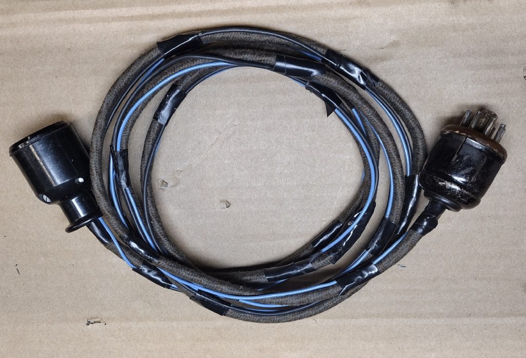
Unfortunately my radio did not come with the Heathkit HP-23 power supply. It seems like as time goes on these power supplies are becoming more difficult to find. At many of the radio swaps I have attend the past few years I have seen more HW-100 and HW-101s than the power supplies themselves. The good news is I have a HP-23A in working order that I previously restored. When I go to Hamvention 2025 this year I will keep my eye out for a good deal on another power supply. However, when purchasing this radio I got lucky and was able to snag the power cord with it. From the picture you can see that someone modified the cord to include a few extra wires. Given that these cords carry lethal voltages I will likely re-wire the cord at a future date. In the past I purchased a replacement cord kit from an ebay seller named radiotyke, these kits set for for around $45 shipped with some assembly required.
Interior Inspection –
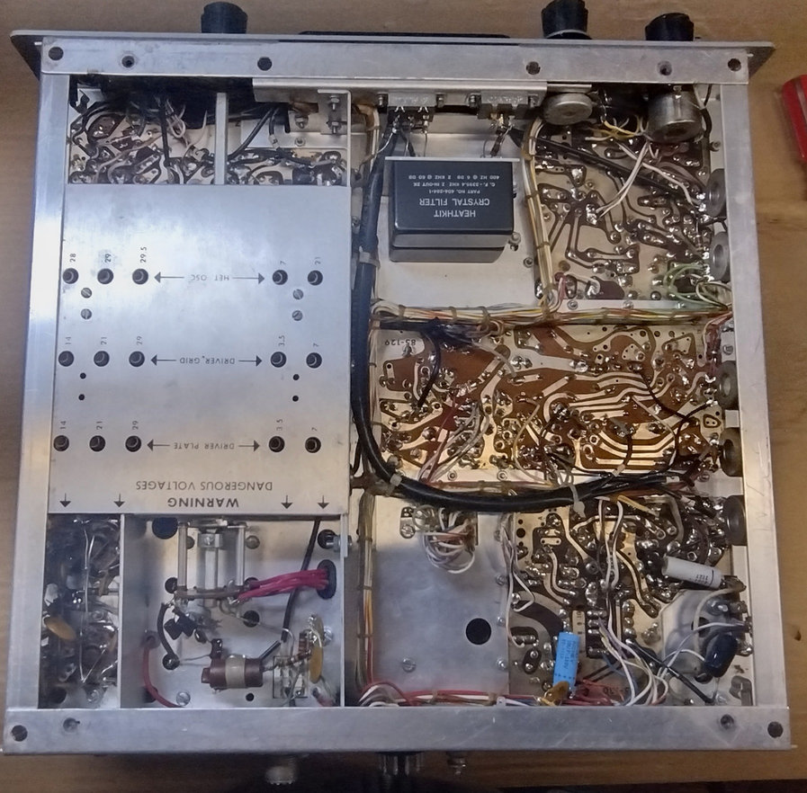
WARNING – The HW-101 and most other tube radios operate at lethal voltages that can kill you. Even after power has been turned off many of the capacitors may maintain a dangerously high voltage over a period of time. When inspecting the radio be sure that power is disconnected from the radio.
I should note that anytime I am looking at a used rig I remove the cover to perform an inspection to see if the tubes are all still present. Since the Heathkit radios were assembled and soldered by the owner as a kit, workmanship can vary wildly from radio to radio, so its important to be able to asses the quality of workmanship that went into the radio before purchasing. If you aren’t able to open the cover prior to purchasing sometimes I shine a flash light through the vent holes to make a rough assessment.
Below are some common areas I generally look for during an interior inspection:
- Are any components, such as tubes or filters, missing?
- How does the assembly workmanship appear?
- Is there any obvious corrosion or other damage present?
- Do any of the components visually appear to have failed? Are any resistors charred or do any electrolytic capacitors to appear to be bulging.
From removing the cover and from an initial observation I was pleased to see that the tubes and tube shields all appear to be present. A previous rig I had worked on encountered some oscillation issues and it took me a little bit of time to realize that this issue was caused by a missing tube shield.
The interior is covered in a substantial layer of dust that while it does not look great should clean up fine later in the wash down process. For many of these radios it is amazing how much dust accumulates in them over the years.
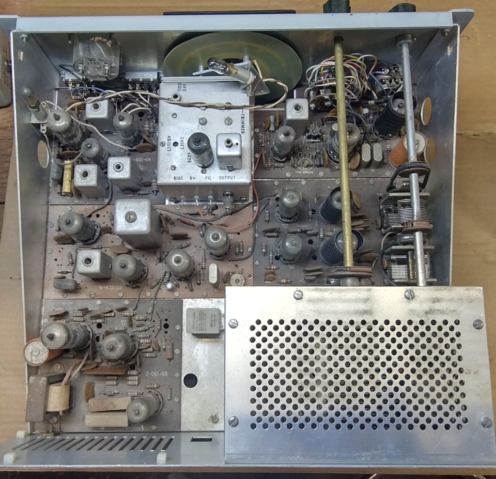
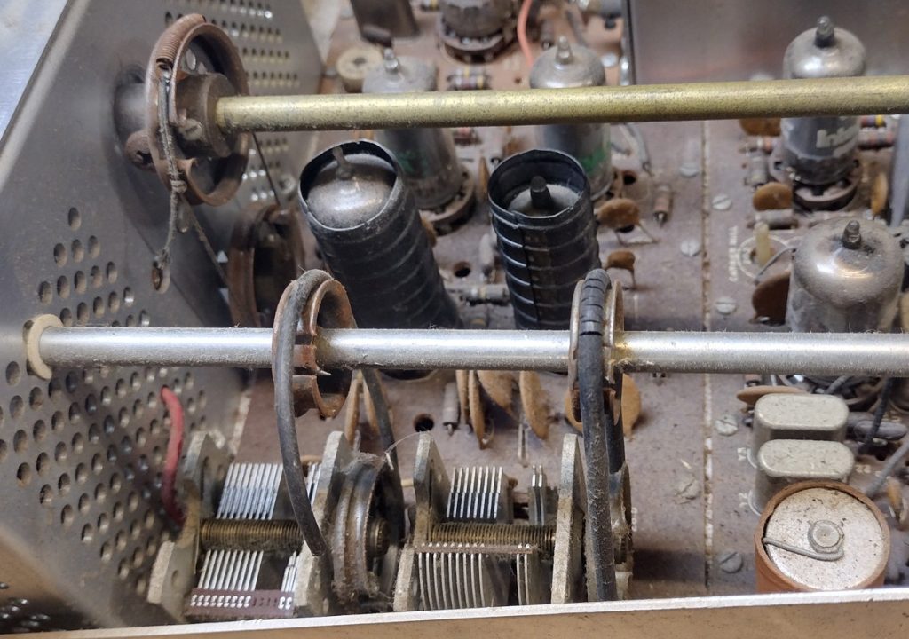
The interior belts appear to have seen better days. One of the rubber belts is broken while the other has a few substantial cracks in it, these issues are all pretty typical for these radios. The good news is that replacement belts can be picked up at a general hardware store for a nominal price or online.
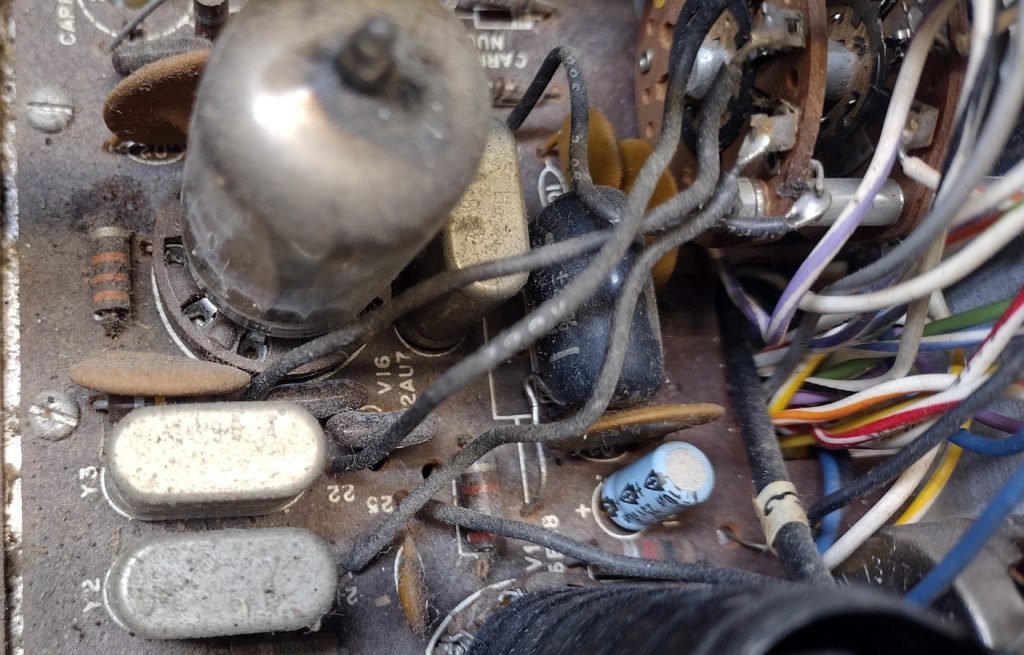
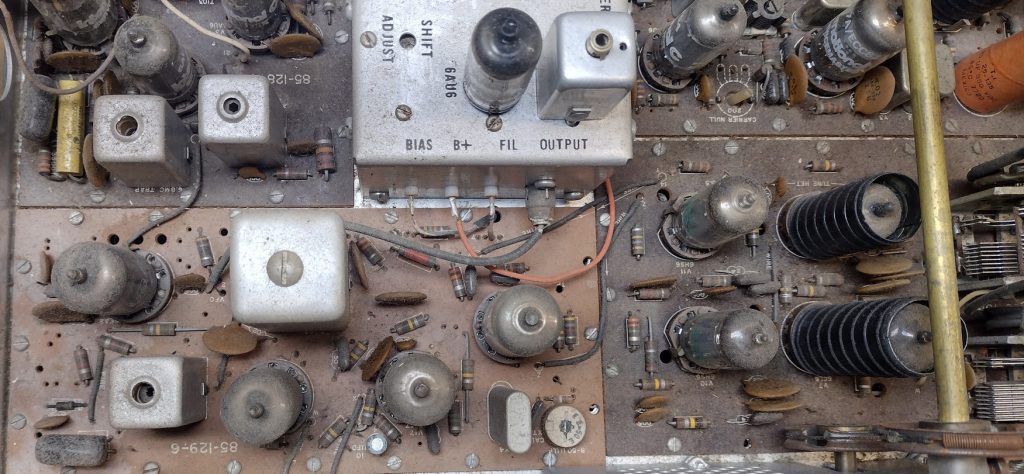
It appears as though at some point in time the radio was re-capped. Many of the original electrolytic capacitors appear to have been replaced. Since I do not know how long ago this work was preformed, as good measure I am planning to completely re-cap this radio. Its a bit difficult to see through the dust but on the top side of the radio there are no obvious signs of damaged or failed components, yet. A closer inspection will need to be performed after the general clean up stage.
As an interesting observation the bandpass circuit board appears to be a different color than the other circuit boards inside of the chassis. This leads me to suspect that this board may have been replaced at some point in the radios history.
Some additional good news, removing the cover off of the high voltage cage I found that the final amplifier 6146 tubes are both present. For this particular radio someone replaced the original tubes with 6146Ws which are the military version of the 6146 tubes. I will be curious to see what the condition these tubes are in. Some claims of bad experiences with 6146B tubes, I have had a few radios with these particular tubes but haven’t seemed to experienced any issues to date.
Removing the bottom chassis cover reveals the bottom side of the radio. Everything on the bottom portion appears neat and tidy. Some of the solder joints appear to have residual flux that was never cleaned but overall there doesn’t appear to be any carnage.
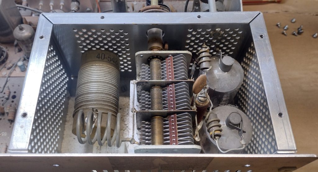
Since this is a HW-101 it includes both the CW and SSB crystal filters and from a quick inspection there are indeed two filters present. If this was an HW-100 it would include just a single filter which is one reason the HW-101s are more desirable.
I removed the shield over the heterodyne oscillator circuit and everything seemed in normal shape. All coils appeared to be in good condition with no visible damage present. These coils can be rather delicate and difficult to come by as far as spare parts go.

Given the completeness and general condition of this radio I think we are good to be in good shape for this refurbishment. In the next step I will discuss performing an initial “smoke test” on a radio and reasons you may want to do this and reasons you may not want to.
’73!