My collection of older tube type equipment has almost happened on accident, I never went in planning to start collecting older boat anchor type tube equipment, over time though it seems to have just happened!
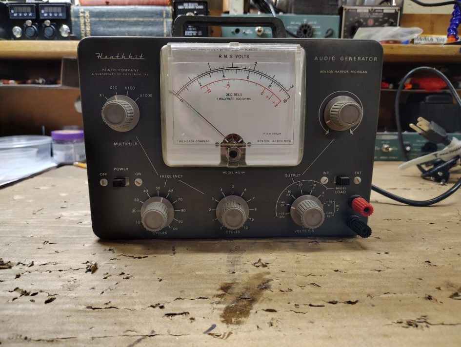
This past summer while at the Kalamazoo ham radio swap I stumbled across a Heathkit AG-9A audio generator with a chassis that appeared to be in excellent condition and the unit appeared to be well kept and taken care of. While working on some of the Heathkit HW-100 series radios I figured it would be handy to have test equipment on hand that would allow me to generate audio tones for troubleshooting or my eventual end goal of building radios.
Inspection and Initial Testing
When getting the equipment home I removed the rear cover and did an initial visual inspection and the workmanship and condition of this equipment seemed positive. I pulled the tubes in the audio generator and put them on a tube test and all tested in good condition. I also tested the instrument incandescence lights and tungsten lamp, its worthwhile to mention that when the unit is operating you should not see a the tungsten lamp glow.
Table 1. Vacuum Tubes
| Tube PN | Function |
|---|---|
| 6X4 | Full wave rectifier |
| 6CL6 | Oscillating Amplifier |
| 6AU6 | Oscillating Amplifier |
Resistors
Each of the resistors was tested against its value in the schematic, if a resistor seemed like it might be a questionable value I de-soldered one leg of the resistor so that my measurements were not being effected by other resistors in the circuit. Most resistors used in this device (unless specified on the schematic) are 1/2W. I was lucky enough to have on hand sufficient replacement resistors on hand in my on hand parts stock.
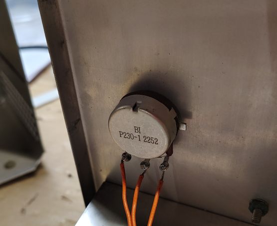
Figure 1. Replacement Output Control Potentiometer
I shot a quick spritz of deoxit fader into each of the 3x potentiometers and tested the resistance of each. I found on my unit that the meter control and oscillation control adjustment potentiometers seemed to be in good condition however my output control potentiometer, which is accessible on the front face was shot. From browsing the inventory at Mouser and Digikey I identified PN: P230-1FC25BR5K as a replacement for this 5k Ohm Potentiometer.
Diodes
As a preventative measure I decided to replace all of the diodes in the 3x diodes in the metering circuit and replaced them with 1N5711 diodes. If replacing these diodes be aware that the Heathkit manual recommends dressing them such that the leads are kept long. I decided to dress my replacement diodes in a similar manner as the original ones were installed on my unit.
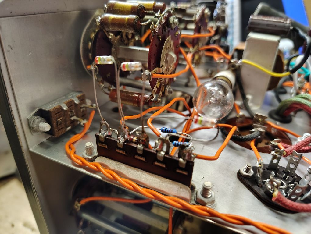
Figure 2. Original Diode – Long Leads
Switches
To clean up the contacts on the rotary switches and on-off switch I gave each a quick spritz of Deoxit. Where the contacts were accessible I used a cotton swap and actuated the switches a few to times to clean them up.
Capacitors
Next I needed to look at the capacitors, I tested each of the precision capacitors in the multiplier circuit. When testing individual caps I was sure to actuate the multiple switch in such a way that it isolated the specific capacitor of interest. From a test here I determined of these capacitors to still be in sufficient condition.
As a common best practice for older equipment, I opted to replace all of the electrolytic capacitors. These capacitors don’t have the longest service life and are common failure points and can fail in a catastrophic manner. To save on shipping costs I generally like to bundle in components from multiple projects, where possible.
Table 2. Replacement Electrolytic Capacitors
| Value | QTY | PN | Notes |
|---|---|---|---|
| 16uF 150V | 1 | EGXF351ELL160MJ20S | |
| 20uF 350V | 1 | EGXF351ELL200MJ25S | |
| 47uf 450V | 2 | ESH476MA450AM7AA | Original value was 40uF. |
When replacing the 20uF capacitor I found it easiest to glue the capacitor to the transformer as a means of fastening it and soldering wires to each of the leads.
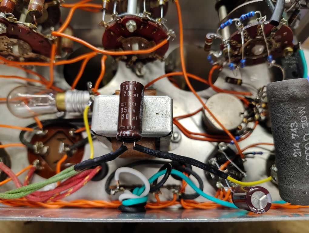
Figure 3. 20uF Capacitor
The original filtering capacitor consisted of a single cylindrical tin assembly that holds 2x 40uF capacitors. As technology has advanced the physical space claim of capacitors has been significantly reduced and the style of capacitor that was originally used on this Audio Generator is obsolete.
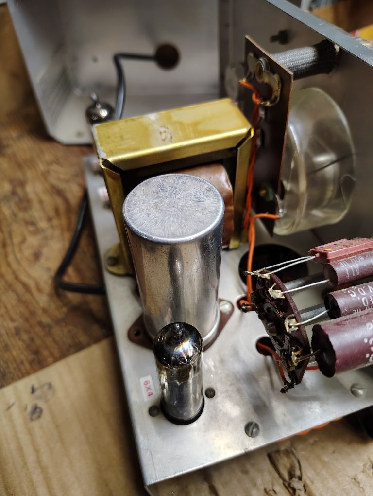
Figure 4. Original Dual 40uF Capacitor
To come up with a suitable replacement I decided to design a PCB that would utilize the same screw mounting pattern include leads similar to the original capacitor but would utilize modern commonly available leaded capacitors. Specifically I decided on using common 47uF Electrolytic capacitors.
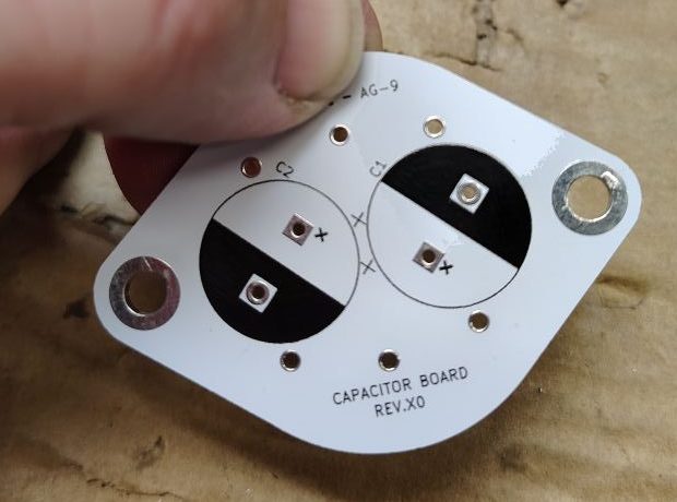
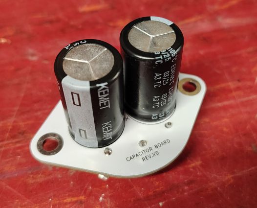
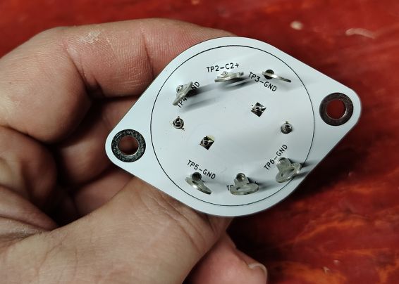
Figure 5. Capacitor Replacement Board
The figure above shows what the end circuit board designs looks like. For this initial revision I realized that I had made a minor but correctable mistake for this initial revision. This mistake was that I connected the plated thru holes used for mounting to ground, given my plan for how I will be connecting the safety ground (see the section that follows), I really need to keep the circuit ground isolated from the chassis on the signal generator. For this revision to act as a fix I will use nylon fasteners and a space washer to keep these grounds isolated. For future revisions Ill keep the the capacitor negative leads/grounds isolated from the mounting screws.
I found the size difference between the original capacitor installed and the replacement remarkable.
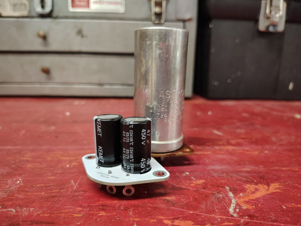
Figure 6. New Capacitor (front) vs. Original Capacitor (rear)
Prior to disconnecting any wires I was sure to take a clear picture of the wires and where they routed to in the event I was unsure when resoldering the wires in place. Desoldering the original wires was a bit tedious. I found it helpful to temporarily remove the bulb on the inside of the audio generator. As I went through the desoldering process I was sure to label the specific wires that were soldered to the capacitor positive leads. Its worth mentioning that the negatives of each of the capacitors connects to 4x common ground connections on the bottom of the new board.
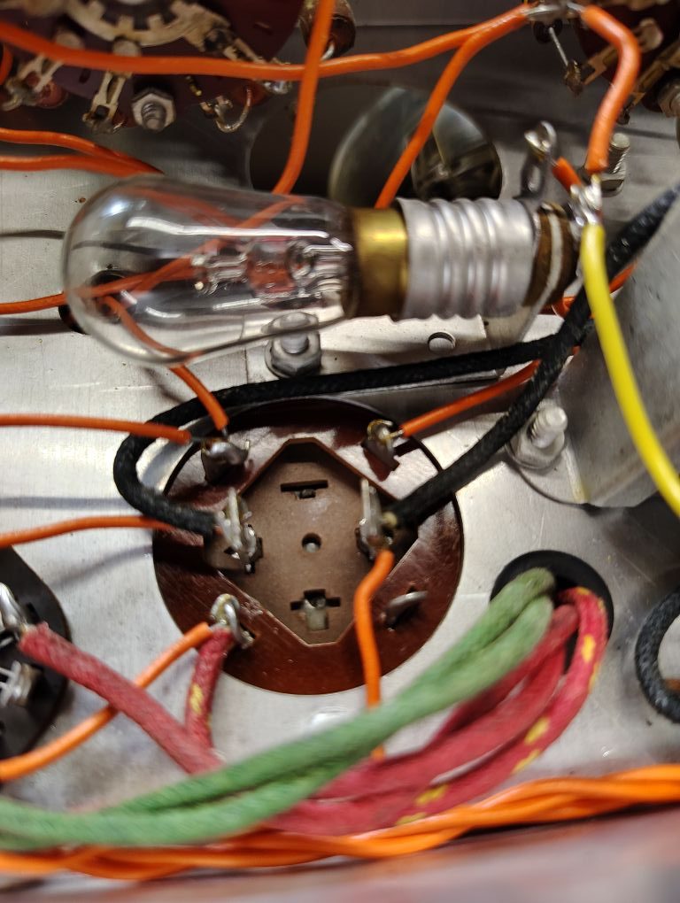
Figure 7. Original Capacitor Wiring
When removing the old capacitor I became a little concerned that the bulb on the inside of the unit may also be another return path through the metal work of the chassis but was relieved after I tested it and it was not.
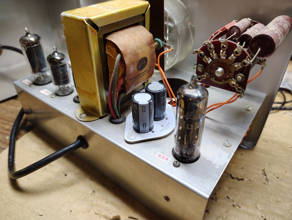
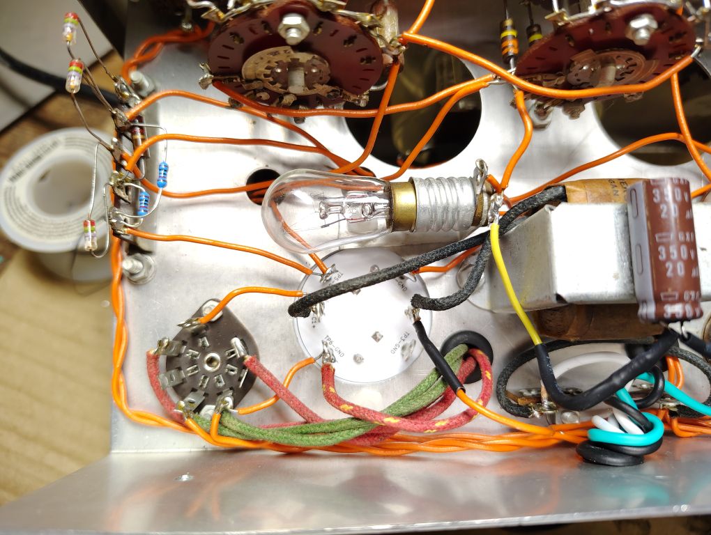
Figure 8. Replacement Capacitor Board Installed
120VAC Plug Replacement
I decided that it would be best to upgrade the power plug from a 2x prong to a 3x prong AC power plug that includes a safety grounding prong. One concern I had with tying the 3rd prong directly to the metal chassis was introducing grounding loops, or an additional return path for current to flow. If you have worked with audio systems and have noticed a hum sound this is likely the culprit.
I used a used 120VAC 3-prong cable from an old computer, removed the C13 style connector and proceeded to strip back the cable jacket. I soldered in the hot (black) wire to the terminal strip location going to the switch and the neutral (white) wire into the terminal location going to the transformer as shown.
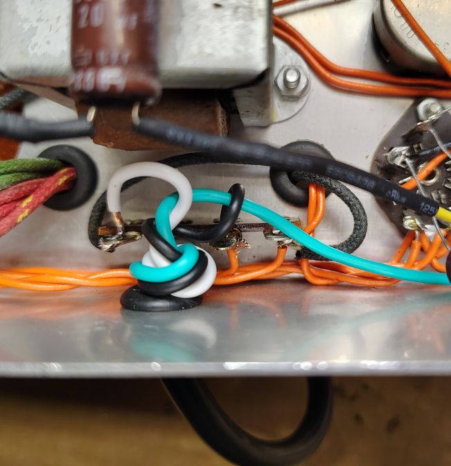
Figure 9. Hot & Neutral Wire Terminal Strip
I routed the safety ground (green) wire to the side of the chassis not far from the audio output banana jacks. I crimped the wire to a ring terminal for a #6 sized fastener. I proceeded with drilling a hole using a 5/32in sized drill bit into the approximate chassis location as shown below. I fastened the ring terminal from the safety ground wire to this newly drilled how using a #6-32 x 3/8LG fastener, 2x #6 flat washers and a #6-32 nut.
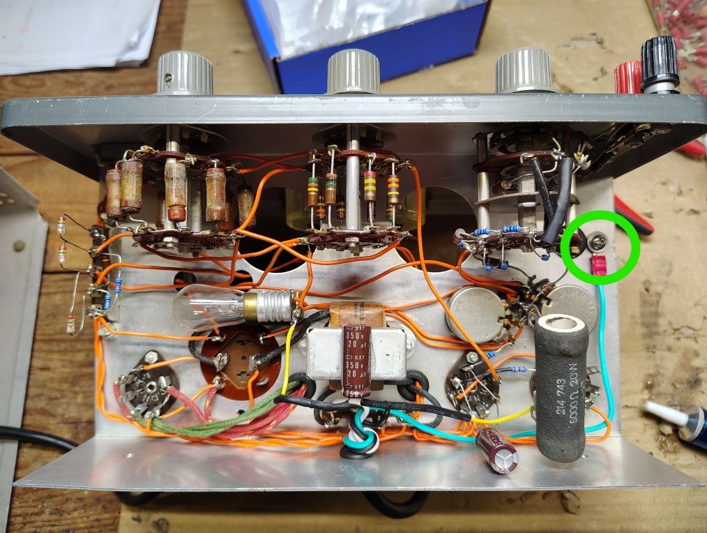
Figure 10. Safety/Chassis Ground Connection
To prevent ground loops with this newly added chassis ground connection I decided to disconnect the existing circuit ground from the chassis ground and place a capacitor between the two. This physical location takes place on the black audio output banana jack. I placed a 0.01uF (or 10nF), 2kV capacitor PN: CGP5C103MDWDAA7301 across the chassis to the black output banana jack. This capacitor block audio or DC level return currents from flowing between the chassis and the negative banana jack but will shunt RF frequencies to chassis ground.
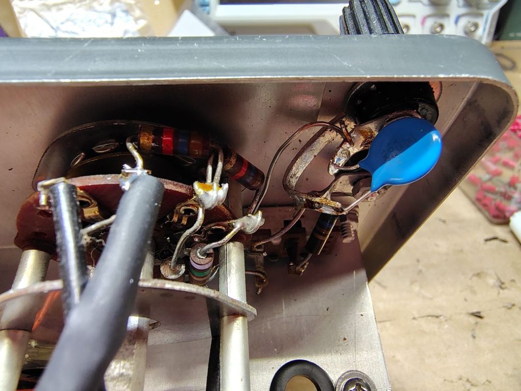
Figure 11. Circuit Ground Capacitor to Chassis Ground
If someone has a better option for this chassis ground connect feel free to reach out, I’m open to opinions here.
Labeling
Some may object to it, but I found it helpful to labeled the tubes and adjustment knobs on the interior of the chassis.
Testing and Adjustment
When powering up a device like this for the first time, I always recommend using a dim bulb tester if you have one. Elsewise as a minimum, I recommend plugging the audio generator into a line that has an additional fuse or circuit breaker lower than your mains 15A/20A breaker.
If you have access to a modern oscilloscope it is really a great tool to use to not only visually see the generated sine wave, but measure the frequency and amplitude (in VRMS ). It’s worth mentioning that the Rigol DS1054 Oscilloscope that I use includes two different frequency counters, one that performs the measurement using hardware while the other that is measured using software. I generally keep both enabled but for most situations the hardware frequency counter accessible by going to Measure > Counter menu is often more accurate.
Prior to powering the unit up I generally place the Output knob in its midway position. Since my oscilloscope is set as a high impedance input I enable the INT 600Ohm load on the audio generator. A few brief moments after power up the generator you should see some deflection on the needle and if your oscilloscope is properly adjusted for time and amplitude a sinewave form should appear.
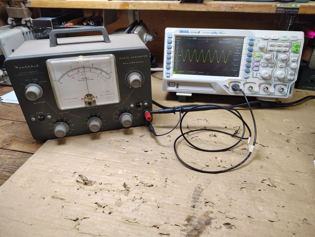
Figure 12. Test Setup
Calibration instructions for the audio generator are included in detail in the Heathkit AG-9A manual but I will summarize them here for reference.
Meter Calibration
With an oscilloscope connected to the audio output, select a frequency between 50-3,000Hz. Adjust the meter control such that the measurement on the meter matches that of the measurement on the oscilloscope. I recommend performing this test at a few different frequencies and output levels.
Oscillator Calibration
With nothing connected to the output terminals, set the audio generator as follows:
- Output Control – Maximum
- Cycle and Multiplier – 10Hz or more
Calibrate the oscillator output by turning the oscillator control to give you just over full scale reading on the meter. Test the needle deflection at a different frequencies between 10Hz-100kHz and if the output drops below full scale on the meter, readjust the oscillator control potentiometer. Be careful not to adjust this potentiometer too high or else you will experience distortion.
Oscillator Calibration
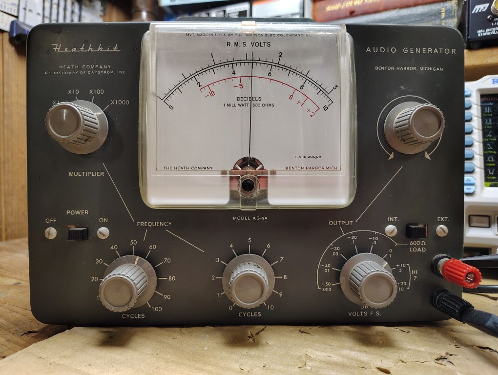
Figure 13. Audio Generator Output
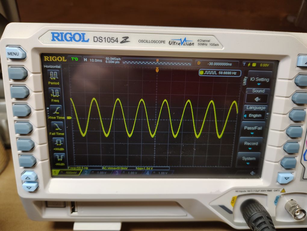
Figure 14. Oscilloscope Measurement
From testing my unit I found it to be surprising accurate as far as the outputted frequency and amplitude. I’m sure I will find many good applications for this newly refurbished test equipment!
’73!