After wiring is complete I always suggest taking a break and prior to testing doing a through check of all of the wiring to the schematic before powering everything up. I like to go through things wire by wire and highly a fresh copy of the schematic as I go through everything. Next install the bottom most metal cover back onto the power supply.
WARNING – The power supply operates at lethal voltages that can kill you. Even after power has been turned off many of the capacitors may maintain a dangerously high voltage over a period of time. Use extreme caution when using the power supply or when troubleshooting.
Before powering the unit up I recommend following the INITAL TEST section in the official Heathkit manual. These steps have you perform some quick and simple resistance measurements. For these measurements I connected my voltage probe up to the chassis ground connector on the 120VAC plug.
The Heathkit manual notes that some more modern solid state DMMs may not provide a sufficient voltage to activate the diodes and recommends performing this step using a VTVM on the Rx10k setting. Some of the readings may take a few seconds to settle as there are capacitors in the circuit that are charging.
Table 1. Initial Testing
| Receptacle Contact Position | Reading |
|---|---|
| 1 | 22kΩ or higher |
| 2 | Infinity |
| 3 | 75kΩ or higher |
| 4 | 75kΩ or higher |
| 5 | Infinity |
| 6 | Infinity |
| 7 | 0Ω |
| 8 | Infinity |
| 9 | Infinity |
| 10 | Infinity |
| 11 | 10k-20kΩ For models with adjustable bias Infinity for models without adjustable bias |
Before powering the power supply up I want to reiterate that this power supply uses voltages that are lethal and when testing or simply using one of these power supplies should be done with due care. If you are not experienced or trained with working with high voltages then do not use the power supply. Be aware that the capacitors in the power supply may hold a lethal charge for a period of time even after the power supply is turned off and the 120VAC power cord is disconnected.
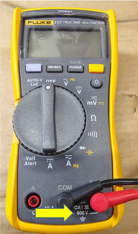
For all testing performed with the unit powered up be sure that all test equipment you use is rated for the voltage of the power supply. For example my Fluke 117 multimeter is only rated for 600V.
I used a 12AWG piece of wire to act as a jumper between the the AC SW and AC common positions on the receptacle.
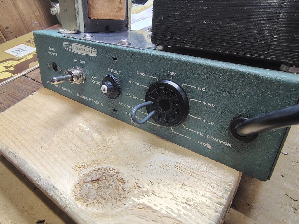
The negative lead of my DMM was clipped onto one of the chassis connected screw terminal. I plugged the 120VAC plug from the power supply into fused power strip and flipped the power switch on the power supply. I carefully probed the receptacle on the front of the power supply with the positive lead the results should be as follows.
Table 2. Power-up Measurements
| Contact | DMM Setting | Measurement | Note |
|---|---|---|---|
| 1 (-130V) | DC V | -130VDC | |
| 2 (FIL COM) | N/A | See contact 6 and 8 test | |
| 3 (+LV) | DC V | ~275VDC ~350VDC | 250DC Switch Position 300DC Switch Position |
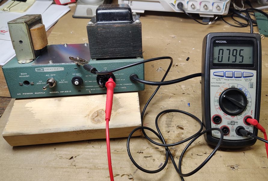
| 4 (+HV) | DC V | ~800VDC | |
| 5 (NC) | N/A | N/A | No connection |
| 6 (12V) | AC V | ~14VAC | For this measurement use contact 2 (FIL COM) for the negative probe |
| 7 (GND) | AC V DC V | 0VAC 0VDC | |
| 8 (6V FIL) (Where present) | AC V | ~6.9VAC (where present) | For this measurement use contact 2 (FIL COM) for the negative probe. |
| 9 (AC SW) | N/A | See note below | |
| 10 (AC COMMON) | N/A | See note below | |
| 11 (ADJ BIAS) (Where present) | DC V | ~ -40VDC to -80VDC | Adjustable using potentiometer |
Notes:
Contact Positions 6 and 8 are both VAC measurements. For these measurements use contact 2 (FIL COM) for the negative probe.
Contact Position 9 and 10 are jumped to power on the device. Contact 10 should be 120VAC when plugged into a 120VAC receptacle and with the toggle switch in one of the ON positions.
Contact Position 11 is only used with certain models, with this feature the BIAS ADJUST potentiometer can be rotated to achieve an output between -40VDC and -80VDC.
After the initial power up test I allowed the power supply capacitors to fully discharge and then proceeded to clean up the wiring underneath. After butting everything up I tested the power supply using a Heathkit HW-100 transceiver and completed the project.