The easiest step for something catastrophic to go wrong during the rebuild phase is during wiring. During this phase is it important to verify every step made to ensure 100% accuracy. Depending on the method and workmanship that the original builder performed you maybe able to keep much of the original wiring. For my build I decided on replacing select wiring to allow for some enhanced wire routes.
WARNING – If you choose to replace any of the wiring for the power supply be extremely mindful on the voltage rating of the wire and the anticipated supply voltage of the power supply. The high voltage line of this power supply exceeds 800V.
Below are the complete 3x schematic sheets that show all of the wiring interfaces. The schematic cover the wiring required in its entirety, Ill only cover a cliffs notes/abridged version in the verbiage below. Note there are some minor difference between each of the model years that Heathkit built these power supplies.

Link to download

Link to download

Link to download
Table 1. Wiring BOM
| Part | QTY | Note |
|---|---|---|
| 2129 3A Circuit Breaker CB1 | 1 | |
| GSW-16 DPDT (ON:OFF:ON SW1 Toggle Switch | 1 | |
| Ring Terminals for #6 Fasteners | 7 | SW1 and safety ground terminals |
| Ring Terminals for #8 Fasteners | 2 | CB1 terminals |
| #6 Flat Washers | 4 | Circuit Board Mounting |
| #6-32 Nuts | 4 | Circuit Board Mounting |
| Wire | AR | Misc colored wire |
| Heat Shrink | AR | Misc sizes |
| 120VAC Cord | 1 | With NEMA 5-15p (3-prong plug) |
Some of the lengths and routings that I used for my wiring may seem slightly excessive however I chose these routes to be of sufficient length for allowing the circuit board to be removed if necessary while keeping the wiring attached.
120VAC Plug Wiring
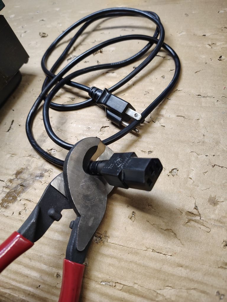
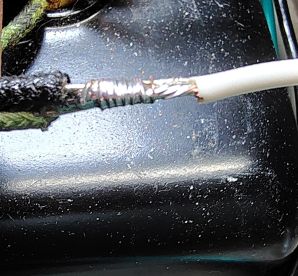
One of the goals for this rebuild was to replace the ungrounded/unpolarized AC plug with a modern 3 prong plug that included a chassis/safety ground. Refer to Figure 2 for the 120VAC Plug wiring. From my spare cable supply I utilized an old computer cable as shown below and removed the C13 connector as shown leaving the standard AC plug.
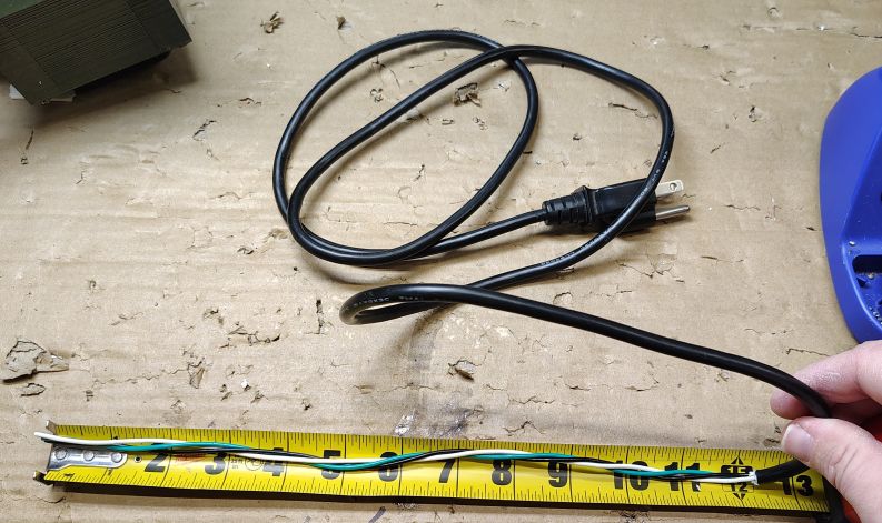
From the cutoff end I carefully stripped the outer cable jacket back approximately 12in while being extremely careful not to nick the jacket on any of the individual wires. With a DMM I pinned out the cable and labeled the hot, neutral and safety ground. Even though my cable was color coded with black, white and green wires I did not want to take any chances.
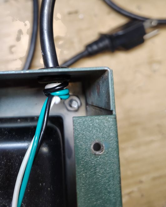
I fed the the cable through the existing AC cable grommet and tied a knot with the wires to act as a strain relief.
To verify the length of the hot I wire, the circuit breaker was temporarily installed and the hot wire was routed to the line terminal on the circuit breaker. With the length verified I terminated the hot wire with a ring terminal for a #8 fastener. I removed the circuit breaker.
To get the length for the safety/chassis ground I temporarily placed the circuit board into the chassis and lined up the 4x mounting holes and routed the wire to the bottom right mounting hole and crimped on a ring terminal for a #6 fastener. The circuit board was removed from the chassis.
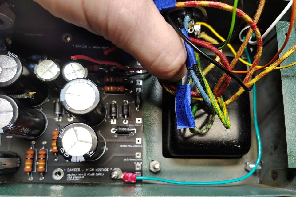
From the wires coming out of the transformer identify the Black and Black-Green wires. These wires get spliced into the neutral line coming from the AC plug. I opted to slide a piece of shrink sleeving over the wires and proceeded to solder a lashing splice.
(Heat shrink not shown)
Receptacle J1 Wiring
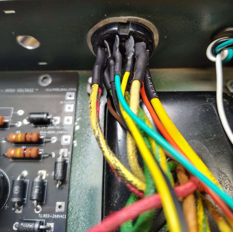
Rewiring for the main receptacle on the power supply can be a bit tricky. For any situations were possible I added a small piece of heat shrink to help insulate the terminal from shorting out with its neighboring terminals. Refer to Figure 3 for a detailed wiring schematic. Note that the illustration of the receptacle is shown When looking into the inside of the chassis with the perspective as shown in the picture below contact position 1 starts going from the dominate key clockwise increasing. I found it helpful to temporarily place the circuit board into the power supply chassis to judge the wire lead length.
Next I wired the receptacle contact 11 to the center terminal on the potentiometer and soldered wires to the first and last contacts of the potentiometer. The opposing end of these wires will connect to the PCB. Reference Figure 1 for the potentiometer wiring.
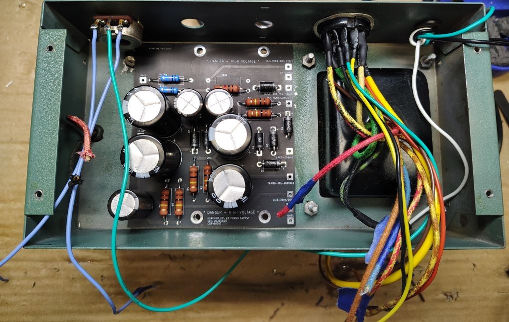
PCB Wiring
Prior to making the wire terminations to the board I cleaned out the inside of the chassis from conductor and solder. The PCB wire terminations are shown in Figure 1. I temporarily placed the assembled PCB into its approximate position and soldered in each of the connections. For each of the wire leads terminating to the circuit board be sure to trim the wire post soldering and ensure it will not short to the chassis.

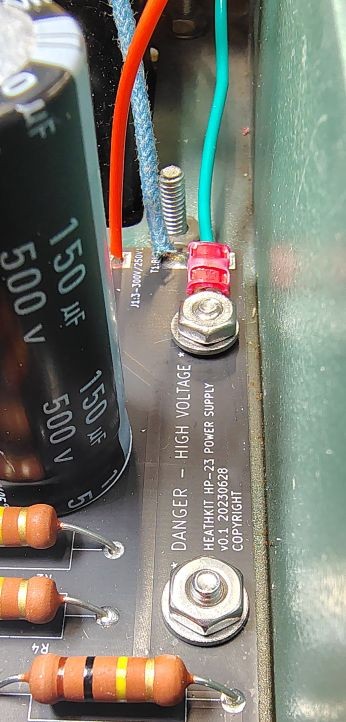
PCB Hardware
I used the following fasteners to fasten down the PCB to the previously installed #6 screws. Note the bottom right screw position is used for the safety ground that gets bonded to the chassis as shown in the picture below.
- 4x #6 Washers
- 4x #6-32 Nuts to act as stand offs for the future installed PCB
Circuit Breaker Wiring
The circuit breaker wiring is shown in Figure 2. The incoming 120VAC hot wire gets terminated using a #8 ring terminal which in turn gets fastened onto the line connection on the circuit breaker. I terminated a wire to a ring terminal for a #8 fastener and connected it to the load connection on the circuit breaker, in a later step this wire will terminate to switch position 5.
The circuit breaker can now be mechanically fastened into place.
Switch Wiring
The last wiring to complete is for the switch. When doing any wiring be aware that the switch keyway gets gets positioned facing outboard on the power supply. Refer to Figure 1 for wiring for the switch. For each of the wires going to the switch I used ring terminals for a #6 fastener. For some situations where 2x wires needed to terminate at the switch I terminated these wires into a single ring terminal.
Next the switch gets mounted to the chassis with the keyway located on the mounting threads facing outboard.
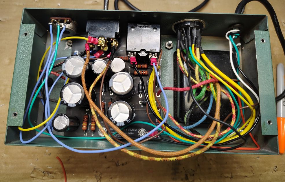
While wiring at this stage may look a bit untidy, I highly recommend waiting to fully dress all of the wiring until a functional checkout is complete. The next step will be to verify the functionality of the power supply.