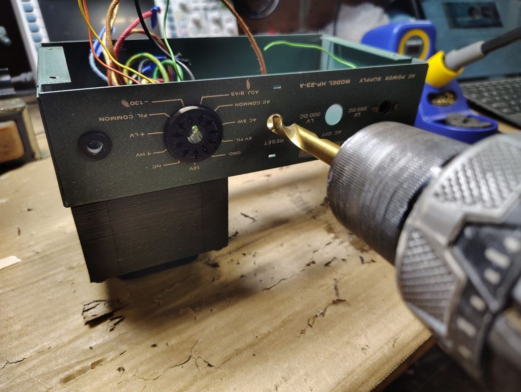
The replacement circuit breaker requires for the chassis mounting hole to be drilled and opened up to a 3/8in hole. When doing this step be sure to protect the wires inside the chassis.
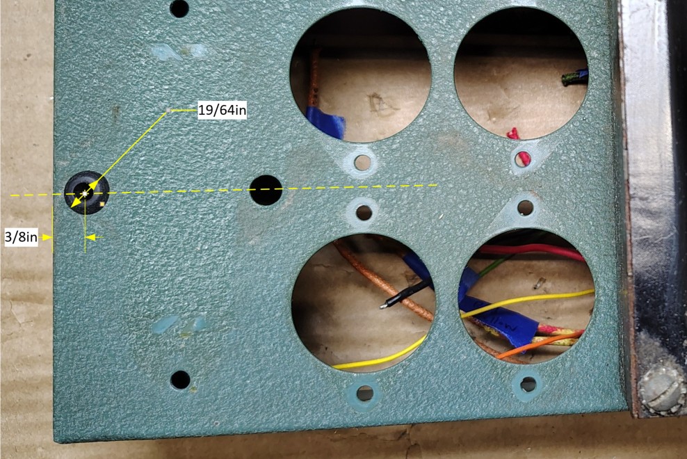
To drill a new hole for the inductor/choke I marked a line denoting the center of the existing hole and marked off a separate line 3/8in from the end of the power supply. To make these lines non-permeant I marked my lines on some blue painters tape. Where the lines intersected I struck a center punch and drilled a new hole using a 19/64in drill bit to mimic the original hole size. If you do not have a 19/64in drill bit a 5/16in should work fine. Reference the picture below for the hole location.
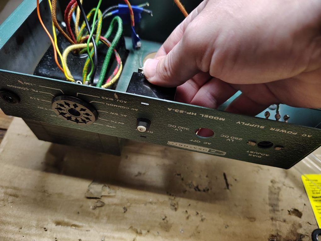
Once the new hole was present and deburred I reinstalled the existing grommet as it was in reusable condition.
If you are going to repaint the chassis you could perform further dis-assembly however for my project I decided this would be a good disassembly stopping point. This is also a good time to clean the exterior of the power supply.
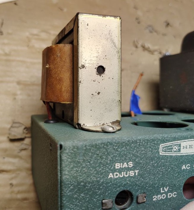
I reused the original fasteners and reinstalled the inductor/choke but installed it 180 degrees from its original orientation as shown below, with the wires exiting the inductor/choke facing outboard. It was helpful to start working the wires through the grommet while getting each of the fasteners on one by one.
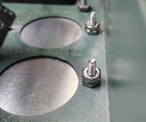
Since the tall electrolytic capacitors that use to stick out of the top the chassis will no longer be used, I fabricated a metal plate to cover the holes and to prevent anyone from being able to touch the bottom side of the PCB that will later be installed. I fastened the plate using:
- 4x #6-32 5/8LG screws
- 4x #6 Flat washers
- 8x #6-32 Nuts to act as stand offs for the future installed PCB
After the PCB is later installed it will be retained with the following additional hardware:
- 4x #6 Lock Washers
- 4x #6-32 Nuts to act as stand offs for the future installed PCB
The next step will cover assembling the circuit board.