WARNING – The power supply operates at lethal voltages that can kill you. Even after power has been turned off many of the capacitors may maintain a dangerously high voltage over a period of time. Use extreme caution when using the power supply or when troubleshooting.
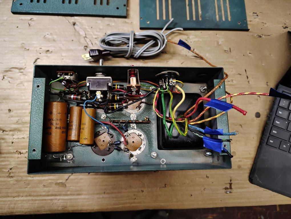
The first step in this process is to remove the old components. I started by removing the bottom cover and visually verified the wires coming out of the transformer and traced each of the wires to their destination. I found it helpful to label the individual wires.
| Wire Color | Destination |
| Red-Yellow | Capacitor C2 – Positive Lead |
| Brown-Yellow / Yellow-Brown | Switch – 275VDC LV Position |
| Brown | Switch – 350VDC HV Position |
| Blue | Terminal Strip – Chassis Ground |
| Black-Green | Terminal Strip – Position with incoming AC line |
| Red | Terminal Strip – Diode D1 / D3 |
| Black | Terminal Strip – Position with incoming AC line |
| Yellow | Receptacle – Contact 2 (Filament Common) |
| Green-Yellow | Receptacle Contact 6 – (12.6VAC FIL) |
| Black-Red | Receptacle – Contact 9 (AC Switch) |
| Black-Yellow | Receptacle – Contact 9 (AC Switch) |
| Green | Receptacle – Contact 11 (ADJ BIAS) Note: Not present on all models |
Table 1. Transformer Wires
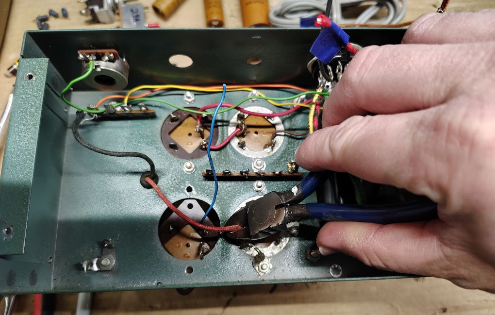
I cut specific individual wires being careful to leave the wire lengths coming out of the transformer as long as possible. The wires cut were as follows:
- Red-Yellow at C2
- Brown-Yellow / Yellow-Brown and Brown at the switch
- Blue, Black-Green, Red, Black at the terminal strip
I would recommend leaving the following wires from the transformer intact:
- Yellow, Green-Yellow, Black-Red, Black Yellow and Green (were present) at the receptacle.
Next I cut the wires coming from the existing AC power cord and removed it completely.
For this modification Ill be replacing the existing switch and circuit breaker. I cut each of the wires and leads going to the existing switch and circuit breaker and completely removed bother components. The circuit breaker is held in by a few tabs that you will need to bend over to remove the component. I used a 9/16in deep-well socket to remove the nut from the toggle switch.
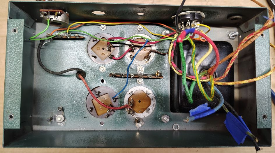
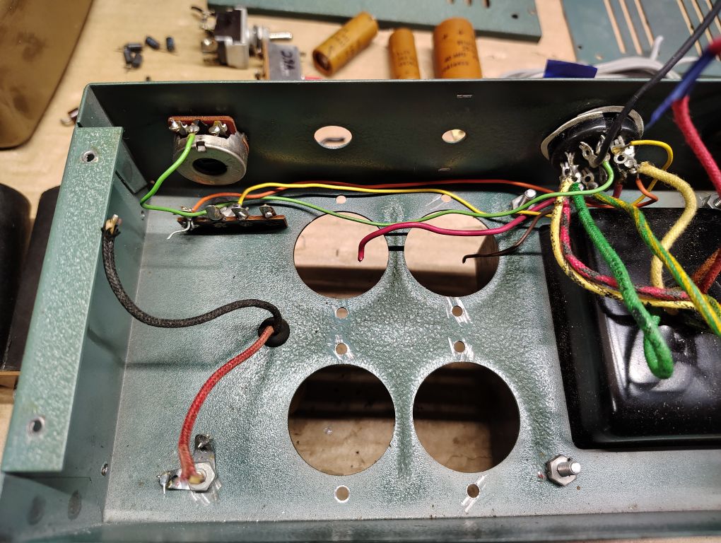
On the bottom side I cut out the old electroytic capacitors, diodes and fixed resistors. Below is what the chassis looks like with these components removed.
The red and black wires for the Filter Choke inductor were located and cut leaving as much length as possible.
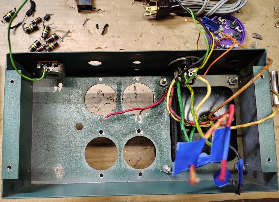
I next began cutting any of the remaining wires that connect up to the topside capacitors of the power supply and began removing these capacitors and the center terminal strip using a phillips head screw driver and 1/4in socket.
I carefully cut the wires at the remaining terminal strip shown in the upper left portion of the picture below.
I proceeded with removing the screws that hold the remaining terminal strip and inductor/choke. When these fasteners were removed I completely removed and retained the inductor/choke using a flat head screw driver and 11/16in socket. The dimensional constrains of the circuit board that I developed, will require, in a future step, for a new hole to be drilled into the chassis for the inductor/choke wires and for the inductor/choke to be installed 180° from its original position. I removed the rubber grommet that protected the inductor/choke wires.
Depending on the scope of your power supply rebuild you can choose to replace the remaining wire going between the receptacle on the power supply and center contact of the Bias potentiometer (for models where this feature is present). Additionally you can choose to replace the remaining flying wires connecting to the receptacle, one advantage to doing so is it allows you to change the wire routing path under the power supply. I opted to remove the now open wire leads that went to the receptacle contacts: 1, 3, 4, 7 and 10.
WARNING – If you choose to replace any of the wiring for the power supply be extremely mindful on the voltage rating of the wire and the anticipated supply voltage of the power supply. The high voltage line of this power supply exceeds 800V.
I used this opportunity to shoot a small spray of cleaner into the bias potentiometer (for models where present). If you have Deox-it fader I would recommend using it for this application.
The next step will be some minor chassis preparation,
’73!