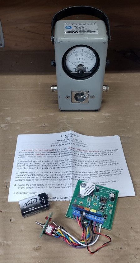
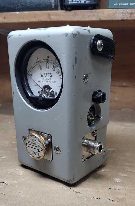
The Bird Thruline 43 Wattmeter is a quintessential piece of test equipment for the RF professional and tinker and is considered to be the timeless standard for measuring forward and reflected RF power. The device have a few downsides. One drawback is the fact that the device will only measure average power, in other words you can use it for measuring the power output from a CW, AM or FM signal but will not accurate measure peak power from a SSB signal. Another draw back of the device is the costly RF elements also known as slugs. Slugs for the device are generally specified by frequency range and full scale power level. Its not uncommon to see used slugs go for over $100 on ebay.
A solution to some of these drawbacks in the B&M Distributors Bird 43 Peak Adapter Kit. I will preface this post by saying that this kit was purchased completely online and was not donated or provided to me for the purposes of this write up. For this post I will discuss my experience with the adapter kit installation and a few challenges I ran into with the installation of this kit.
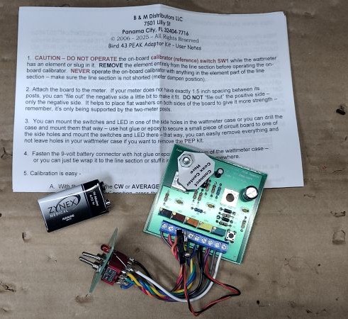
While there seem be many clones of this peak kit at ham swaps and on ebay this particular kit was purchased from ebay seller jimmcjr. A peak kit add on does exist from Bird Electronics however its well known that this kit eats through 9V batteries.
Some of the advantages to using this kit include the ability to switch between average and peak power and the ability to multiple the full scale power reading of each slug by 2x or 5x. This feature alone pays for itself as the peak kit can be had for around the same price as a more inexpensive slug.
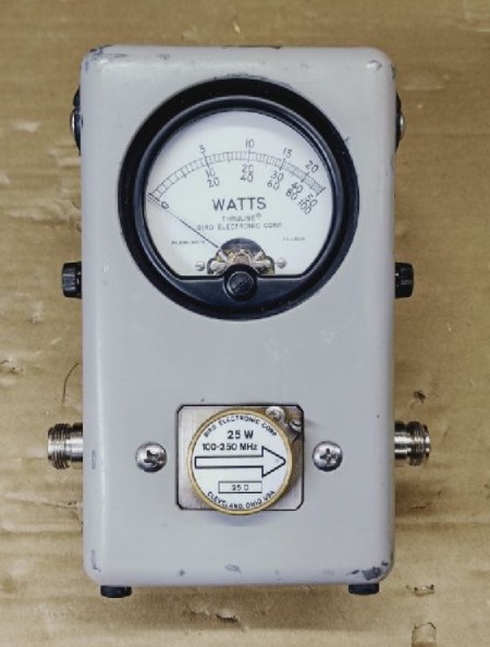
Prior to installing any type of aftermarket accessory like this I always recommend testing your Bird Wattmeter for functionality prior to performing the modification, this way you know if there is a problem with your equipment prior to performing a modification or whether your modification caused a problem.
To perform the upgrade begin by removing the 4x screws that hold the rear portion of the enclosure. From opening up the enclosure you can see there is really not much when it come to complexity for the Bird 43 besides a current meter, line unit and slug.
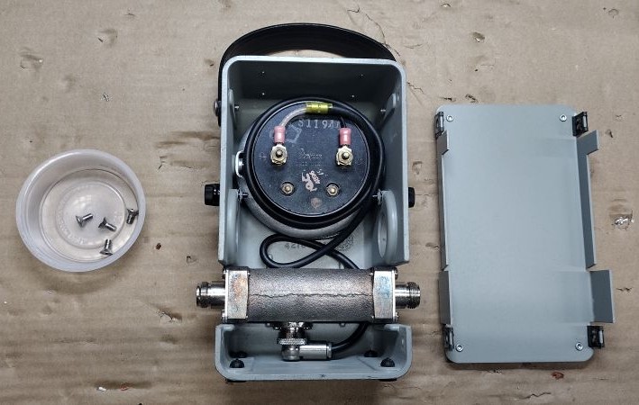
The next step is to disconnect the coax connections to the meter unit. The meter has excess coax coiled inside it in the event the user wants to remotely install the line element from the meter. From performing a quick fit check I found that I needed to slightly adjust and recoil the coax to get the fork terminals positioned exactly how I wanted them.
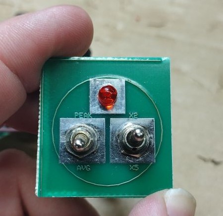
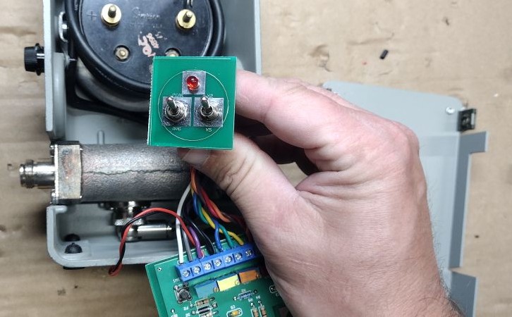
One area of improvement for this kit is the mounting for the switch assembly. The instructions call for either drilling out the Bird enclosure and using a fastener for mounting the switch board or hot gluing it in place. For my installation and for future possible ease of removal I decided to hot glue the board into place. Prior to attempting to glue the switch assembly in-place I highly recommend doing a quick test fit and highly recommend temporarily removing the RF line element. When I attempted to install myn I had to work to apply the glue swiftly maneuve the swithc board assembly into place around the obstacles in the enclosure. I feel like this kit could be improved by including a simple plastic part that clips into place.
Next I positioned the circuit board assembly onto the meter. From a quick observation I found that the circuit board, when placed onto the meter would now physically interfere if a slug was placed into the side of the Bird 43 chassis. To resolve this issue I placed some spacer washers between the meter and the circuit board, doing so seemed to provide just enough roof for a slug to slide into place and barely not come into contact with the board terminals. Next I fastening the nut onto the positive meter stud. I next attached the negative/coax shield onto the corresponding positive meter stud. From placing the spacer washers between the board and the meter I found that I was not able to achieve an additional thread and a half above the fully fastened nut however I deemed the thread engagement to be sufficient enough for my usage.
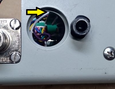
The positive or coax center conductor then gets installed onto a post on the board board appropriately named “Coax Center Here”. For my board I found that the fork terminal for the positive center conductor was smaller than the terminal provided on the board, the fork terminal can be replaced or you can attempt to slightly open up the terminal hole using a drill. If choosing to drill out the terminal use extreme caution, if your drill catches on the terminal you will place stress on the wired connection which could lead to future failures.
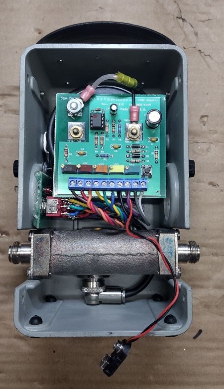
The next step was to install the 9V battery. I feel like the kit really could use a mounting strategy for the included 9V battery. The instructions call for hot gluing it to the case or zip tying it to the line element. For this installation fed a zip tie around the RF line segment and snugged up the zip tie and connected the battery to the circuit board connector.
When I plugged in the battery I noticed the red LED on the switch assembly illuminate. This LED seems to turn off for a low power sleep state to prevent against excessive battery drain when the switch is in the AVG setting.
Prior to using the kit it will need to be calibrated. To perform this calibration you will need a small flat head screw driver to adjust the trimmer pots. For each of the calibration steps ensure that no slugs are loaded into the unit and the slug port remains empty. The calibration of the device was not too difficult, essentially you setup the switches as described in the manually, press and hold SW1 on the circuit board and adjust the the trimmers for the required meter deflection. The most difficult part of this process was to hold down SW1 while adjusting the trimmers, all on the backside of the meter while trying to read the meter value on the front side. The calibration steps can be summarized as follows:
Table 1. Peak Meter Calibration
| PEAK/AVG Switch Setting | X2 / X1 / X5 Switch Setting | Potentiometer to Adjust | Meter Target |
| AVG | X1 (Center Position) | VR3 (ORANGE) | FULL SCALE DEFLECTION |
| PEAK | X1 (Center Position) | VR2 (BROWN) | FULL SCALE DEFLECTION |
| AVG | X2 (Up Position) | VR4 (YELLOW) | 50 OF 100 SCALE READING |
| AVG | X5 (Down Position) | VR5 (GREEN) | 20 OF 100 SCALE READING |
| AVG | ANY | VR2 (RED) | USED FOR ADJUSTING NEEDLE HANGE TIME |
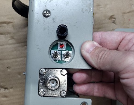
To wrap things up I reinstalled the 4x screws that fasten the rear cover to the Bird 43 meter. The next step was to perform some testing on the meter by measuring the power output from a radio and testing the power multiplier settings.
In summary the Bird PEP kit adds some helpful functionality to a Bird 43 wattmeter by allowing it to measure PEP or peak power and will extend the power measuring capability of the slugs to X2 or X5 of the original specified slug value. While performing this modification I did find that there is some room for improvement for this kit. The mounting for the switch board assembly and 9V battery could be improved above and beyond simply gluing them into place, the terminal for the coax center conductor stud should be made smaller and the circuit board should be made shorter so that it won’t interfere with a slug positioned into the side storage location.
’73!