
What is the Alignment Process?
The alignment process is a series of adjustments that help maximize the performance of the radio. This multistep process will include steps such as peaking the heterodyne oscillators and nulling out the carrier from the final RF signal to properly adjusting the VFO so that your radio is on the correct frequency.
The manual for the HW-101 goes through these steps in detail. If you are looking for a video of walking through these steps check out Will Everett N5OLA’s YouTube channel.
Tools Needed
- Alignment Tool Set GC8454 – Specifically tools GC8282 and GC9300
- Volt ohm meter
- Dummy Load (QTY 2)
- Wattmeter
- Frequency Counter
- Oscilloscope with FFT – This is a nice to have but is not required, alternatively a volt ohm meter with a RF probe will suffice.
- Additional HF radio with a spectrum/waterfall display – This is not absolutely required but is extremely helpful to have.
WARNING – The HW-101 and most other tube radios operate at lethal voltages that can kill you. Even after power has been turned off many of the capacitors may maintain a dangerously high voltage over a period of time. Use extreme caution in powering up the radio especially if covers are removed.
If you plan to probe any of the high voltage points on the radio be sure that your volt ohm meter can safely handle the voltage that is being probed as of the high voltage lines are 800VDC.
S-Meter Adjustment
Setup the radio as follows:
- Driver Preselector: Top position (12 o’clock)
- MIC/CW Level: Fully counterclockwise
- Mode: LSB
- VFO: 200
- Function: PTT
- RF Gain: Fully clockwise
- Meter: ALC
- AF Gain: 9 o’clock position
Locate the Zero ADJ potentiometer on the right side of the radio. Adjust the potentiometer until the S meter reads zero.
Hetrodyne Oscillator Initial Adjustment
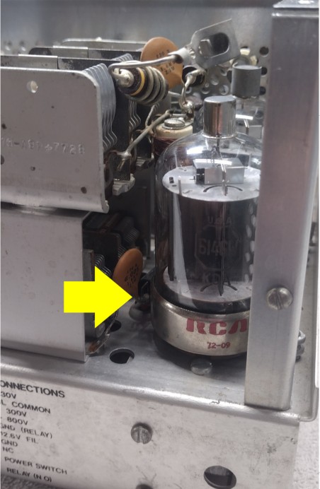
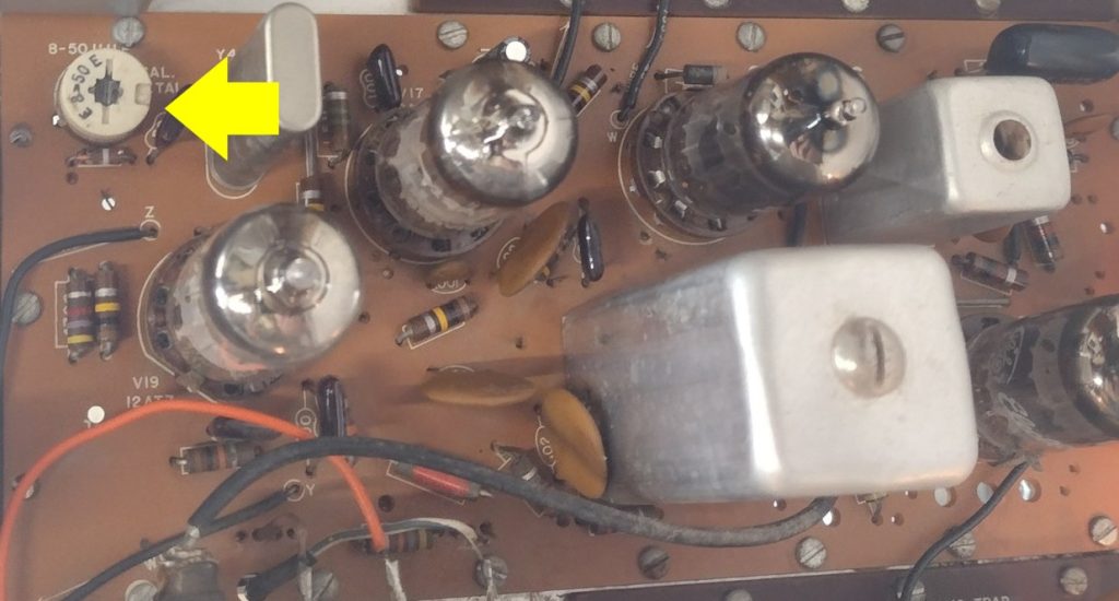
For these measurements use a DMM on the DC voltage setting, using an alligator clip, clip the negative lead to the chassis. Insert the positive lead into the TP hole (near V19), this location is shown in Figure 1 below.
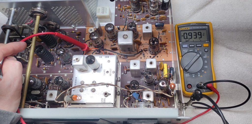
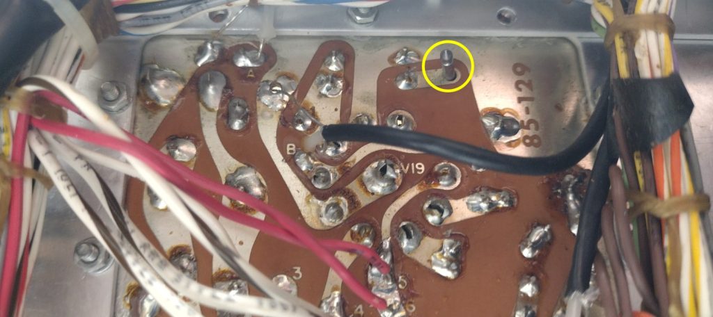
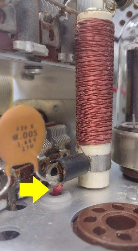
You should see a voltage between -0.5 to -5VDC. Starting with the band switch on 3.5Mhz and perform the measurement. If you don’t see a voltage here be sure to angle the positive probe (it makes contact with the foil below). A few of the circuit board foil that the test probe needs to be contact with is shown below is Figure 2.
Using a GC9300 alignment tool, adjust the value to be between -0.5 and -2.0VDC. Perform this process for each band the radio covers.
Note the heterodyne oscillator adjustment locations are:
- Top side of board: 3.5Mhz, 14.0Mhz and 28.5Mhz
- Bottom side of board: 7Mhz, 21Mhz, 28Mhz, 29Mhz and 29.5Mhz
Transformer Coil Adjustments
Setup the radio with the following settings:
- Function: CAL
- Meter: ALC
- VFO: 400 – Note: Adjust the VFO until you are able to hear to the tone of the calibration signal.
- Driver Preselector: Top (12 o’clock position).
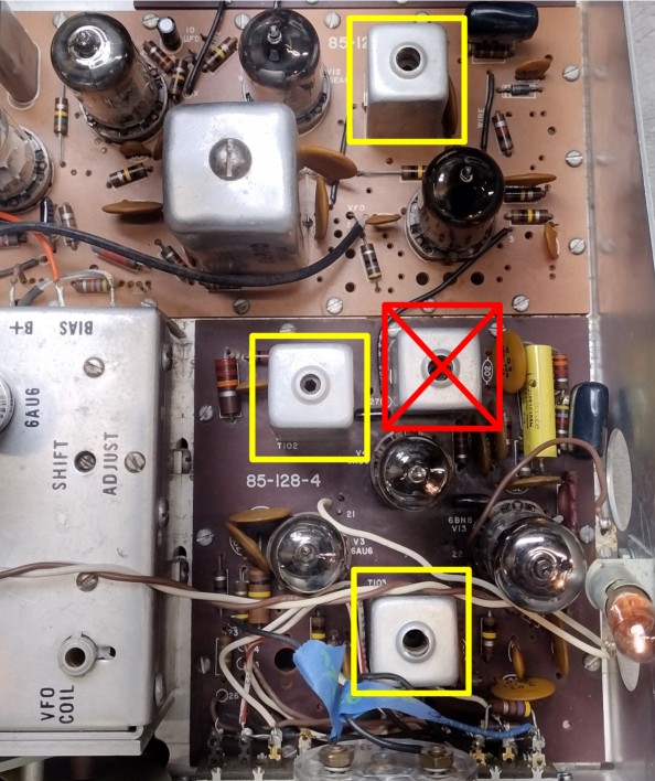
A GC8282 alignment tool will be used for this step. Observe Figure 4 and note the transform locations, T201 (top), T102 (middle left) and T103 (bottom) Adjust T201 and T103 for the maximum audio able volume and needle deflection. Next adjust both the top and bottom slugs for T102 for maximum needle deflection and tone volume.
During this step be careful and DO NOT the 6.8MC Trap. This trap is shown below in Figure 4 in the middle right.
VFO Alignment
Before performing this step allow the radio to warm up for approximately a half an hour. Prior to this period of time the radio is subject to drifting.
The VFO has two adjustments that are as follows:
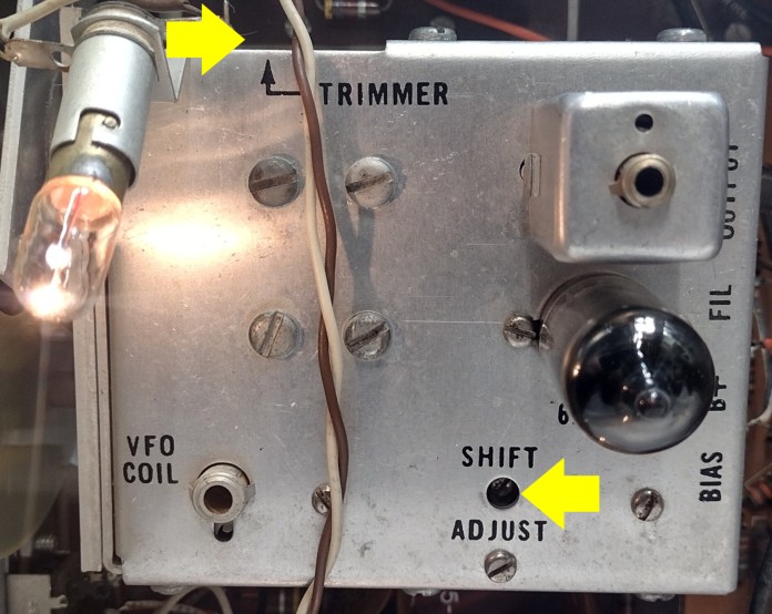
- Trimmer
- Narrows the entire VFO frequency span – By turning trimmer clockwise
- Widens the entire VFO frequency span – By turning trimmer counterclockwise
- Shift Adjust
- Decreases Frequency – By turning adjustment clockwise
- Increases Frequency – By turning adjustment counter clockwise.
As a basic setup for this step I connect the radio to a dummy load and probe the RF output using my oscilloscope measuring frequency mode. To perform this step I utilize BAND 3.5Mhz and set the MIC/CW setting for a low output level and tune the radio accordingly for proper output.
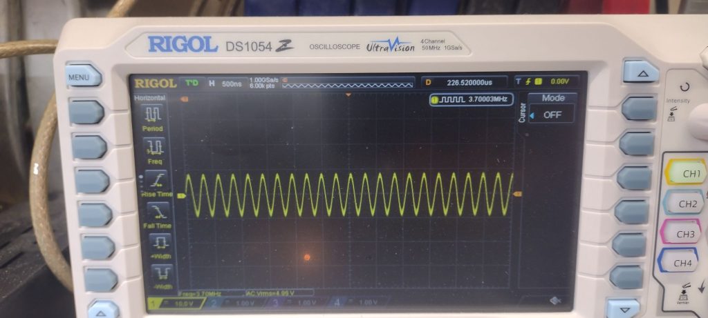
Adjust Trimmer and the shift adjust such that the VFO is accurate for 3.50Mhz, 3.75Mhz and 4.00Mhz
Driver Grid and Plate Coils
The Driver Grid and Plate coils are adjusted on the bottom side of the radio using a GC9300 alignment tool. If during these steps any of the coils appears to be difficult to rotate, DO NOT force coil to rotate. The coils are very delicate and susceptible to being damaged. I have not attempted it but some fellow hams have reported that applying a little heat to the coil with a heat gun may help get the coil to rotate more freely rotate.
Set the radio as follows:
- Band: 3.5
- Function: CAL
- Meter: ALC
- VFO: 200 – Note: Adjust the VFO until the tone can be heard.
Adjust the grid coil 3.5 and driver plate coil 3.5 for maximum S meter indication.
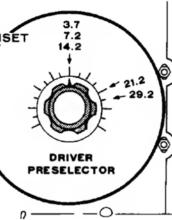
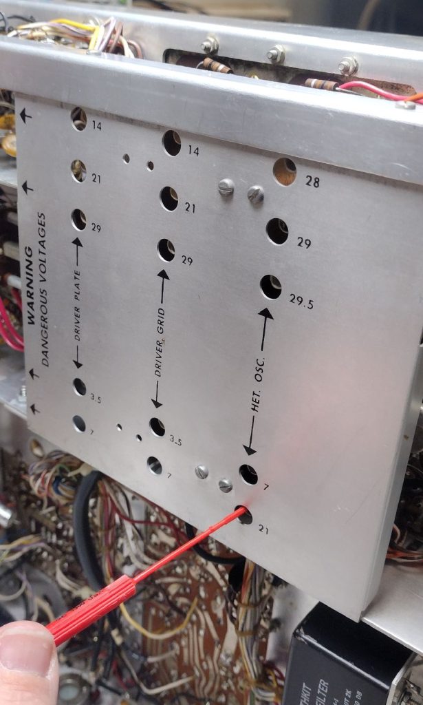
Set the Driver Preselector to the position shown in Figure 7 above for 29.2 and change BAND to 29.0. With the VFO set to 200, slightly adjust the main knob until the calibrator tone can be heard. Adjust the grid coil 29 and driver plate coil 29 for a maximum S meter indication.
Set the Driver Preselector to the position shown in the Figure above for 21.1 and change BAND to 21.0. Again with the VFO at 200 slightly adjust the dial until the calibration tone can be heard.
Set the Driver Preselector to the position shown in the Figure above for 14.2 and change BAND to 14.0. Again with the VFO at 200 slightly adjust the dial until the calibration tone can be heard.
Set the Driver Preselector to the position shown in the Figure above for 7.2 and change BAND to 7.0. Again with the VFO at 200 slightly adjust the dial until the calibration tone can be heard.
Transmitter Alignment
For the next adjustments connect the radio to a suitable dummy load.
Bias Adjustment
Set the radio as follows:
- Band: 3.5
- Driver Preselector: Top (12 o’clock position)
- MIC/CW Leve: Fully Counter Clockwise
- Final Knob: 10 o’clock position
- Final Lever: 4 o’clock position
- Mode: LSB
- Band: 3.5
- VFO: 200
- Function: PTT
- Meter: Plate
Connect a microphone up to the radio. Press PTT and adjust the BIAS trimmer on the right side of the radio until the needle points to the △ (triangle symbol). Next set the METER switch: REL Power and key the microphone. The needle should be at 0.
T1 Adjustment
For the next steps ensure that the radio remains connected to a dummy load.
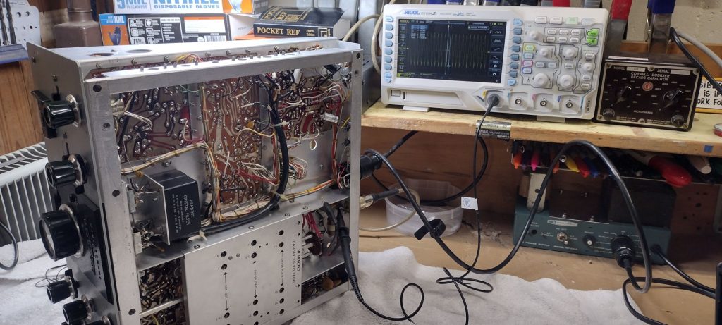
There are a few different ways to perform the next measurement. I personally like to perform these steps using an Oscilloscope connected to the RF line just inside of the radio chassis with the negative lead clipped onto the chassis. For these measurements I will be using a Rigol DS1054 oscilloscope. I set the probes to AC coupling and set the voltage scale to 10V. For some of the later measurements I will enable and use the frequency counter feature on scope.
Set the Band switch still on 3.5 and the MIC/CW Level fully counter clockwise. Switch the radio into TUNE mode and slowly increase the MIC/CW level until you can see a response on the oscilloscope. Adjust the Driver Preselector for maximum output. Next adjust the FINAL tune knob for maximum RF output. Adjust the MIC/CW level until the S meter reads no more than S-3.
Using the GC8282 alignment tool, adjust the T1 transformer to peak the RF output. Reduce the MIC/CW Level meter and again adjust the T1 transformer to peak it out.
Neutralizing the Final Amplifiers
The original instructions in the HW-100/HW-101 for neutralizing the final amplifiers was superseded by a revised procedure that is included in the Heathkit service bulletin titled “ALTERNATIVE METHOD OF NEUTRALIZING THE FINAL AMPLIFIERS”.
As mentioned earlier keep in mind the voltages especially in the high voltage cage are lethal.
Prior to performing this step ensure that the radio is completely off, disconnected from the power supply and has ample time for the high voltage capacitors to fully discharge. To err on the side of extreme caution I will often stop working on the radio for the day and give the evening for the radio capacitors to fully discharge. Yes this is a bit extreme but I would rather stay cautious.
I start by temporarily removing the rear most 6146 final amplifier tube so that I can get access to the 800VDC wire going into the high voltage cage. Using a soldering iron I desolder and disconnect the 800VDC wire and carefully insult the wire. When powered up we do not want this 800VDC line to come into contact with the cabinet chassis ground.
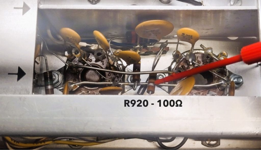
Next I temporarily disconnect R920 which is the 100Ohm resistor shown below on the bottom side of the chassis. If in doubt on which specific resistor needs to be disconnect probe it with a DMM on the ohms setting to verify you are disconnecting the correct resistor. Position the resistor so that it is isolated and does not come into contact with the chassis or any other connection.
Reinstall the rear most 6146 final tube back into place.
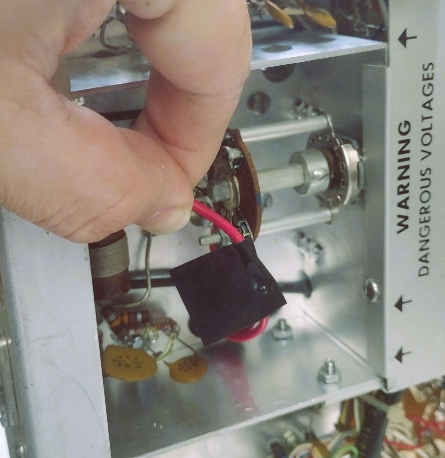
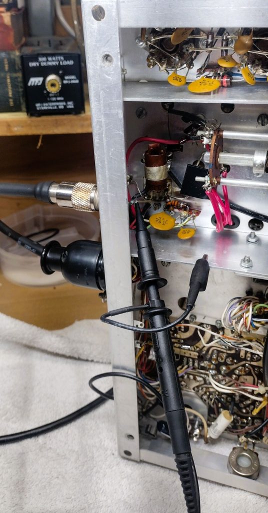
The Heathkit service bulletin calls for using an RF probe and VTVM (Vacuum Tube Voltmeter) inserted into the RF connector. I follow a slightly modified process and connect the RF port to a 50ohm dummy load and probe the RF line of the radio using an oscilloscope, see Figure 8 above for my setup for this measurement.
Reconnect the radio to a power supply and power up the radio. Set the radio to the 28.5Mhz band. Adjust the MIC/CW Level control to the fully clockwise position. Move the radio into TUNE mode. Adjust the the preselector control to maximum reading on the oscilloscope. Next adjust FINAL setting for maximum reading.
Locate the neutralizing capacitor adjustment screw. With the radio in TUNE mode use an insulated screw driver to adjust the neutralizing capacitor adjustment screw to minimize the reading on the oscilloscope.
While the Heathkit manual calls for performing the neutralization process with the Band setting at 28.5Mhz in a past case I had a radio that would breakout into oscillation. For the problematic radio the solution seemed to be neutralizing the radio specifically in the 14Mhz band.
Next allow the radios high voltage capacitors to deenergized. Once safe, reconnect the red high voltage wire in the RF cage and reconnect resistor R920, 100Ohm that we previously disconnect. When reinstalling both of these I try to position these in such a way that would make it easy for my myself to again disconnect in the event the radios finals need to be reneutralized.
Carrier Null
Next we will work to suppress the carrier that is generated by the radio. Locate the Carrier Null Adjustment potentiometer and Carrier Null capacitor. Set the radio to 3.5Mhz and adjust the Mic/CW level to the lowest setting possible. Connect the radio to a dummy load and probe the RF line with a RF probe or oscilloscope. Using LSB mode key the microphone and adjust the potentiometer for a minimum reading. Next adjust the variable capacitor for a minimum reading.
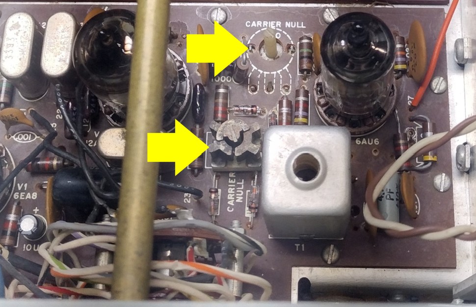
Repeat the adjustments but for USB. Adjust until the USB and LSB settings until the null is approximately the same level. The Carrier Null adjustment potentiometers are known to fail and generally a little Deoxit will not resolve. In a future post I will try to include some details on replacing this component.
Heterodyne Oscillator Peaking
For this step ensure a dummy load is connected to the radio and a watt meter. Set the radio as follows:
- Band: 3.5
- VFO: 200 (for a frequency of 3.7Mhz)
- Meter: Rel PWR
- Mode: Tune
Band to 3.5, and VFO to 200 (for a frequency of 3.7Mhz), METER switch to and the radio into TUNE. Adjust the DRIVER PRESELECTOR and FINAL TUNE and LOAD to maximum output.
Using a GC9300, adjust the heterodyne oscillator coil for maximum output on the slow side of the peak.
Note the heterodyne oscillator adjustment locations are:
- Top side of board: 3.5Mhz, 14.0Mhz and 28.5Mhz
- Bottom side of board: 7Mhz, 21Mhz, 28Mhz, 29Mhz and 29.5Mhz
Repeat this procedure for each band.
Crystal Calibrator Adjustment
For this step I connect a dummy load the output of the transmitter, speakers or headphones to the radio and clip my oscilloscope onto the output lead of the transmitter. Set the FUNCTION to CAL mode and set the frequency of the radio to 3.7Mhz and I set my oscilloscope to measure frequency and place the radio in TUNE. Adjust the MIC/CW level to an amplitude that can be comfortable read on the oscilloscope. Slightly adjust the VFO until I get a 3.700Mhz reading on the oscilloscope.
Next locate the the crystal calibrator adjustment and adjust until the signal just fades away and you have a zero beat.
Verifying Transmit and Receive
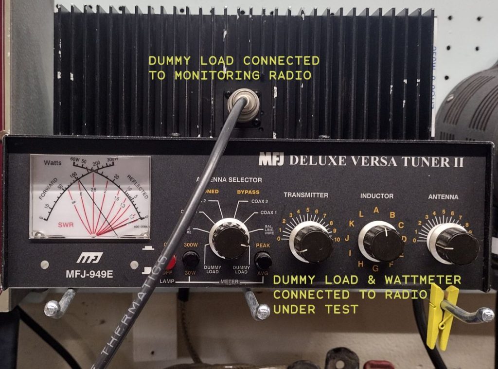
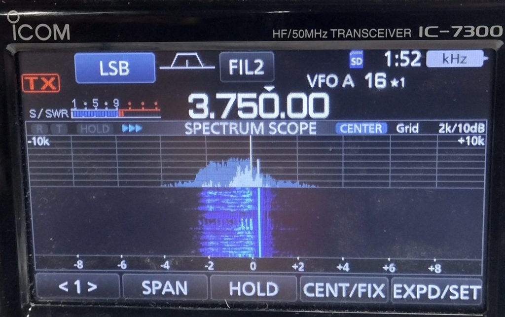
To verify transmit and receive I connect my HW-101 up to a dummy load with a built in watt meter. To help with verifying transmit and receive I use my IC-7300 connected to a second dummy load. I place the two dummy loads near each other. For both transceivers there is enough coupling between dummy loads that will allow you to test the transmit of one radio and receive it in a second radio and not too much coupling to damage the second radio. Using a receive radio with a waterfall will also allows you to visually see the the spectrum from the transmit radio and see issues.
I start by testing the radio in the 3.5Mhz band by setting the radio as follows:
- Band: 3.5Mhz
- MIC/CW Level: Counter Clockwise (lowest setting)
- Driver Preselector: 12o’clock setting
- Final: 3.5
- Inc Load: Counter Clockwise
I next place my second monitoring radio on the same frequency. I place the radio under test in TUNE mode, while watching the watt meter and rotate the MIC/CW Level meter until I start getting deflection on the watt meter. Next I adjust the Drive Preset for maximum output. Next adjust the FINAL for maximum output and INC load accordingly. You should be able to see the output of the radio on the monitoring radio and be able to verify the full power output on the watt meter. For most bands in tune mode you should see 100W when everything is properly adjusted.
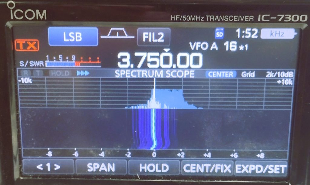
I transition the radio under test out of TUNE mode and into LSB mode. I transmit and speak into the microphone while watching the watt meter and while listening and visually watching the spectrum on the second radio. Next I transmit using the IC-7300 and make sure the receive audio sounds as expected on the radio under test. I follow the same steps for USB mode and CW.
I next follow the same procedure testing each bands. Note that the radio usually outputs less power, ~75-80W on 10 meters.
For this radio I was able to verify power output Transmit and receive on all bands. While testing in USB mode I did notice that the carrier was not fully nulled so I took the opportunity to make these adjustments.
Over the Air Test
Once the bench test is complete nothing beats getting the radio actually on the air and making some contacts and in the end finishes proving the rig out.
When things don’t go quite right…
When powering up the radio doesn’t go right or work out as expected we need to perform some troubleshooting. In the posts the follow I will cover some repair and theory of operation of the radio that can help with troubleshooting.
’73!