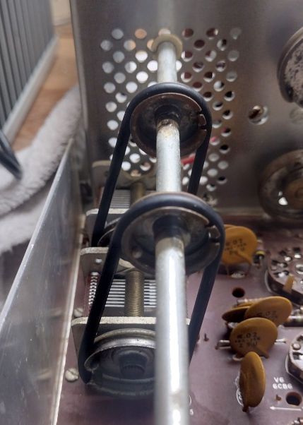
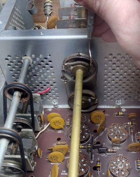
Pulleys
As good measure I replace the O-rings used for the driver pre-selector. These are available either in an O-ring kit or from your local hardware store, with a size of ID: 2in OD: 2-1/8in. Using incorrect sized o-rings can cause issues with the variable capacitors. If the o-rings are too tight arcing can occur with trying to adjust the Driver Preselector, this will manifest itself as a higher pitch hissing (almost like static).
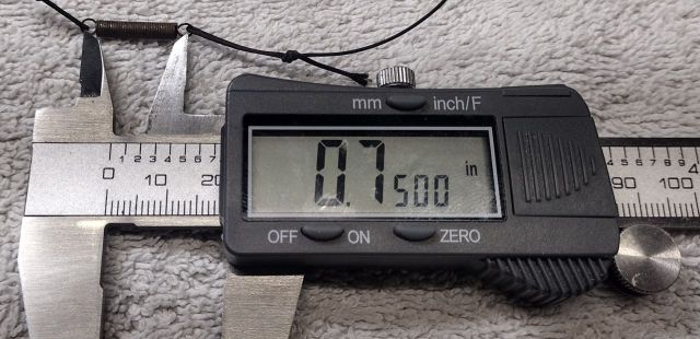
The Heathkit manual provides directions on tying a new dial cord. If you need to replace the dial cord spring the dimensions are: Length: 3/4in (From loop end to loop end), Overall Diameter: 1/8in and Wire Diameter 0.018in.
If you do need to restring the dial cord I have provided an excerpt from the Heathkit manual below that shows the length and knots to use.
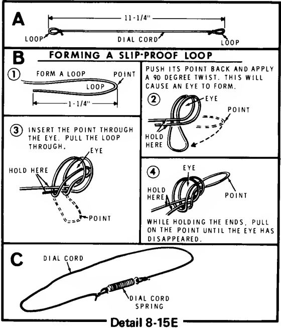
Installing a new dial cord is tedious and challenging, I use a dental pick to try guide the cord to wind it properly around each of the pulleys.
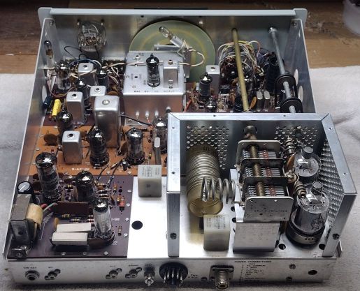
Vacuum Tubes and Lamps
Prior to installing reinstalling the tubes I take one last remaining look over the internals of the radio to make sure no excess metal pieces landed on any of the circuit boards such as trimmed leads from the replaced resistors or electrolytic capacitors.
The next step is to carefully reinstall each of the vacuum tubes that tested as good, carefully one at a time. I generally perform this work sequentially starting with V1 and working my way up. As a reminder be sure to install the tube shields onto V1, V6 and V7.
After the tubes are all loaded into place I installed the pilot lamps. If the lamps are missing or damaged they need to be replaced as their load is important for the vacuum tube circuit to properly operate.
At this point I like to take a brief moment and look at the radio and marvel on the before and after. While this rig isn’t quite in brand new condition it is in much better shape than when we started!

Next Steps
Make sure that the metal shield plate is installed over the Heterodyne Oscillating board, on the bottom side of the radio.
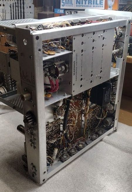
At this stage I leave the remaining chassis panels removed. When we go to perform the alignment process we will need access to the bottom and top portion of the radio. With the high voltage used for the tubes, especially in the high voltage cage one needs to exercise extreme caution to avoid getting an electrical shock.
’73