
Background
In the fall of 2024 I acquired a Bird Termaline Wattmeter-dummy load from an estate of a former electronic tinker. This specific gentlemen’s estate included a sizable allotment of test equipment, components and many scattered Motorola radios all in various states of decomposition.
Given my current equipment I didn’t have a specific need for the wattmeter-dummy load, however, given the bargain price of $20 simply could not pass it up.
When I got the device home I cleaned it up and found that the watt meter only measure half of the RF power output that I was expecting. A little digging on the internet yielded me information on similar models but not much information specifically on the 6154 model that I had on hand. As with any good deal in this hobby, getting used equipment functioning is often a project.
What is the device?
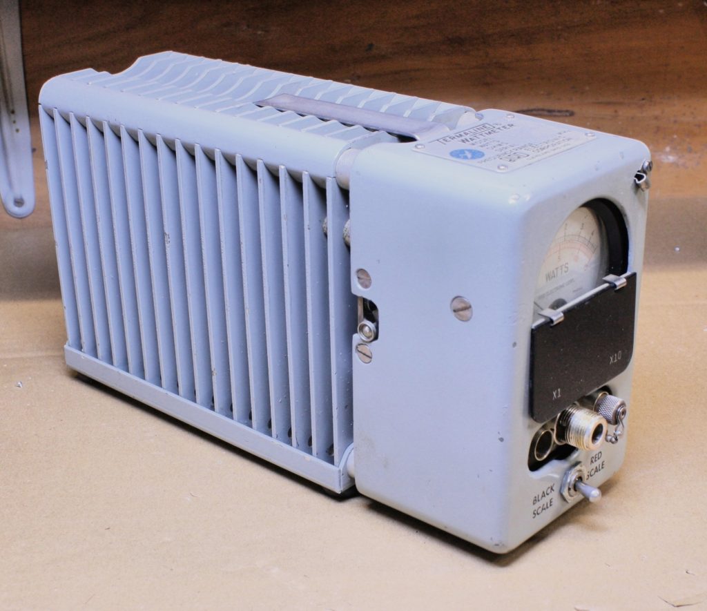
Bird’s Termaline Wattmeters are a combination RF wattmeter and dummy load all-in-one unit. The equipment is handy for measuring the power output of a RF transmitter and can also be used as simply a 50 Ω terminated load for performing work on a transmitter and simulates a typical “ideal-resistive matched” antenna load.
Similar units
The 6154 model has many similarities to its younger and older sibling models such as the Bird 6100 Series (61/611/612), 6104 and 6156 models. The Termaline series appeared to have been manufactured in the 1950s by Bird. From some basic research I was not able to pin down the specific time period Bird manufactured the model 6154 however I was able to locate a few magazine advertisements from the late 1970s that make mention of the unit.
It should be noted that many similar model units differ in the RF power capacity and may utilize different internal resistor and crystal diode values. The current ranges for the meter assemblies may vary as well between the different units.
As time progressed newer models such as the Bird Termaline 673x series included a line section voltmeter block, similar to the line section you would see on a Bird 43 watt meter but without a slug. Bird no longer appears to sell the combination wattmeter dummy load as a single unit.
Specifications
- Frequency Range 25-1000Mhz
- Selectable Measurement Ranges: 5/15/50/150W
- Maximum Load: 150W (Continuous)
- Impedance: 50Ω
- Connector: Type N
- Accuracy: +/-5%
Features
For field work the 6154 includes a handle and cover to protect the glass of the meter assembly. The dummy load is oil cooled and will allow the load to dissipate 150W continuously. If desired the power meter can be remotely mounted using the included 3 1/2ft length of cabling. It should be noted that this specific meter is intended for measuring average power for modulations CW, AM or FM. The 6154 will not measure modulations such as single side band (SSB) that vary in amplitude.
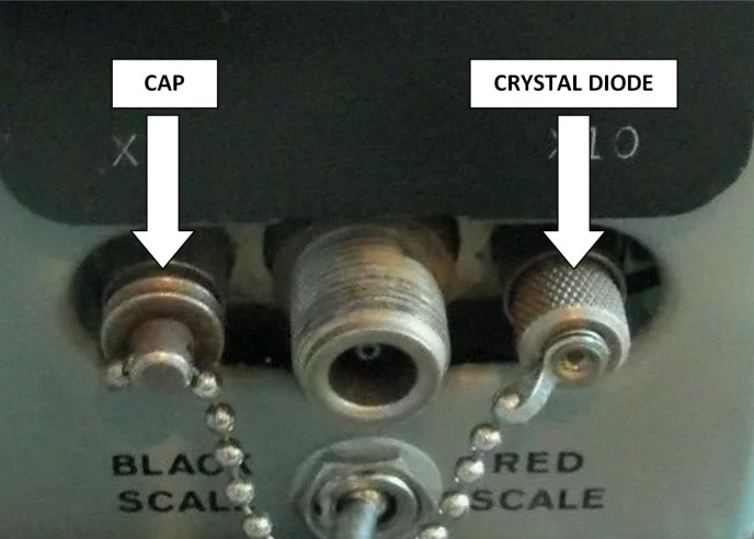
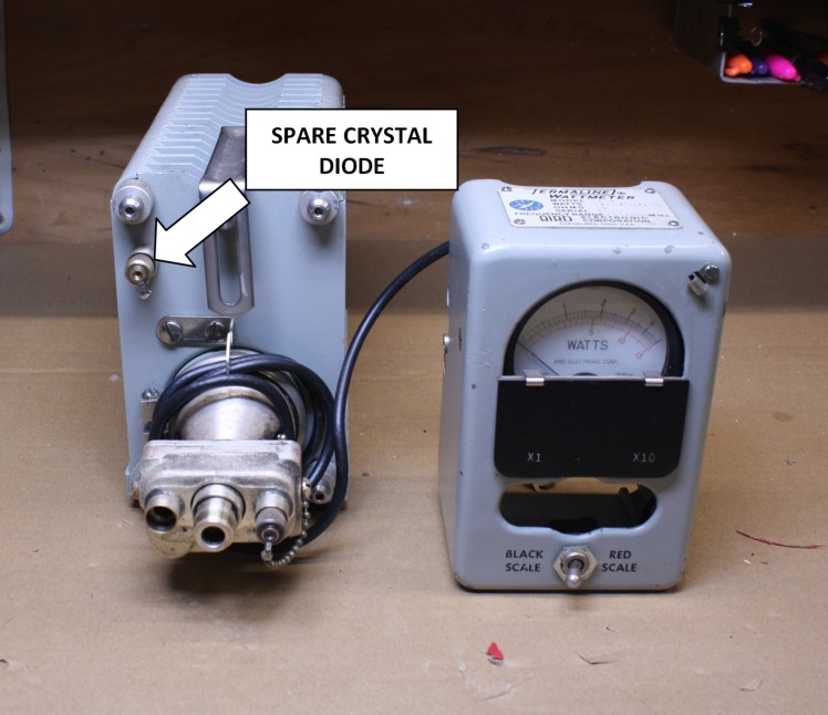
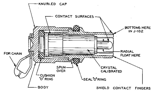
When new, the 6154 would include two crystal rectifying diodes with one being attached to a ball chain lanyard on the front of the unit and the second, spare being loaded into the spare socket somewhat hidden behind the meter assembly. It should be noted that the crystal diode pairs were selected due to their similar characteristics and Bird recommends not interchanging these diodes. The diode assemblies are difficult to find so take care in not mis-placing the primary or spare. The manuals also mention that the 1N79 diodes are susceptible to ESD damage so be extra careful when handling. A cap was also provided with the equipment for us with the unused diode port.
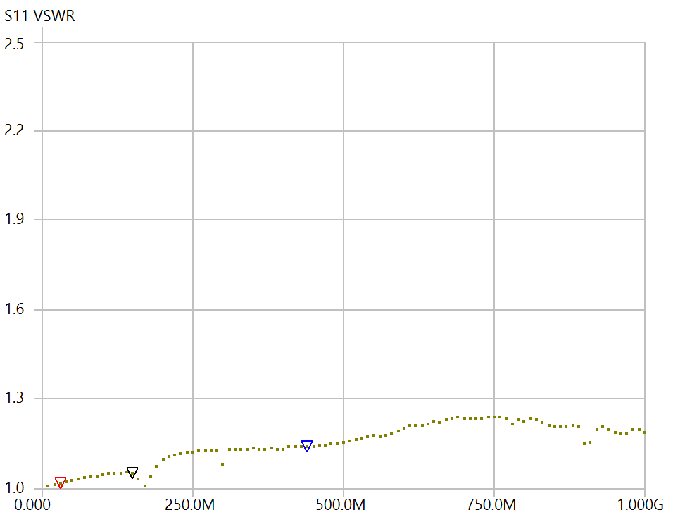
If the user intends to just use the 6154 as a dummy load, the watt meter can be completely disconnected and removed. The manual indicates the dummy load is usable from 0-4Ghz. Using a NanoVNA I performed a VSWR sweep from DC-1Ghz and the VSWR was well below 1.3:1 across the entire band.
Reference Manuals
Bird Electronics includes some legacy manuals for the Termaline models on the discontinued section of their website:
Link: https://birdrf.com/Links/Discontinued-Manuals.aspx
Internet Archive Link: https://archive.org/details/manualsplus_03348/page/n5/mode/2up
Typical Operation
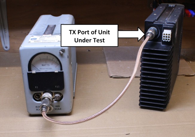
A coax cable is connected from the RF output port on the transmitter unit under test to the RF port on the 6154.
When using the equipment the operator needs to be mindful on the power output from the transmitter unit under test and select the range of measurement accordingly, using too low of a power setting could risk pegging and damaging the meter assembly.
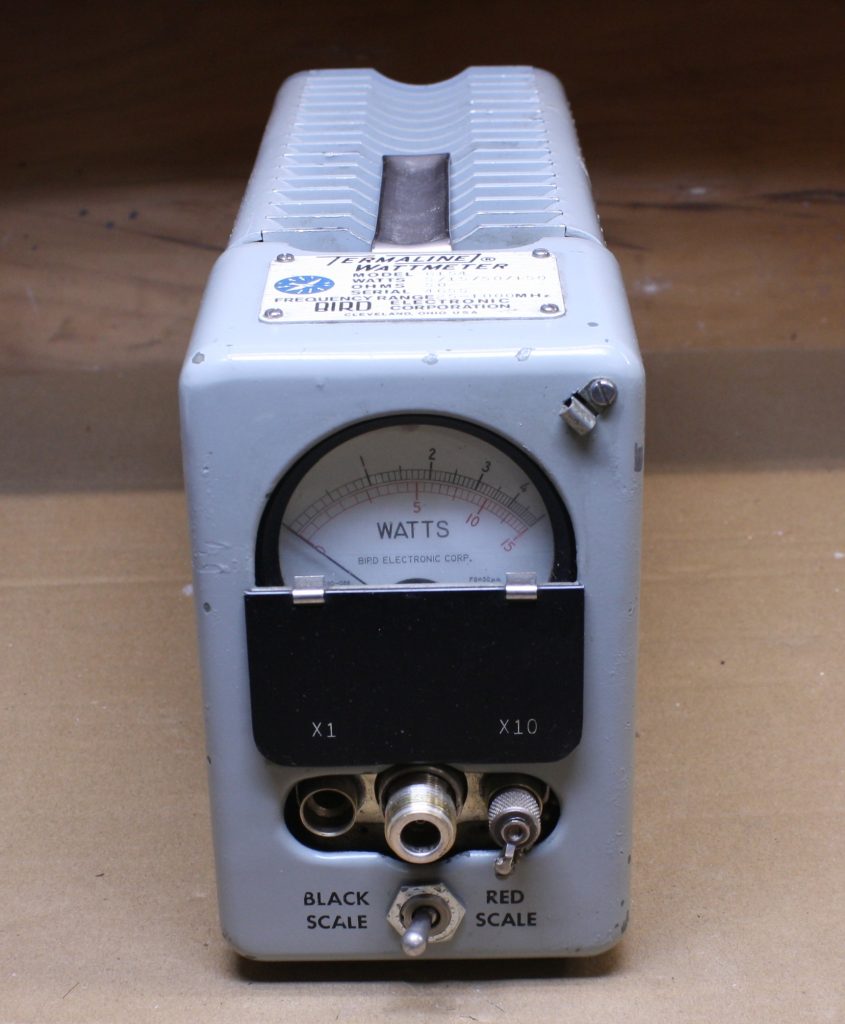
This model features 4 separate measurement ranges, these measurement ranges are selected by the toggle switch position and the port (X1 or X10) for which the diode is inserted into. Once these settings are configured the operator can key up the radio using either CW, AM or FM modulations.
| Power Range (Watts) | Toggle Switch Position | Diode Position | Meter Scale For Measurement |
| 0-5 | Black Scale | X1 | Black (Top) |
| 0-15 | Red Scale | X1 | Red (Bottom) |
| 0-50 | Black Scale | X10 | Black (Top) |
| 0-150 | Red Scale | X10 | Red (Bottom) |
Theory of operation
The schematic for the 6154 was unfortunately not published in the manual provided on Bird’s website. From performing a tear down of my unit and from reviewing the schematic of similar models I have create what I believe to be the schematic for this unit. One discrepancy that I noted was that much of the Bird documentation seems to show the diodes in the opposite orientation, if anyone has any insight on this please let me know.
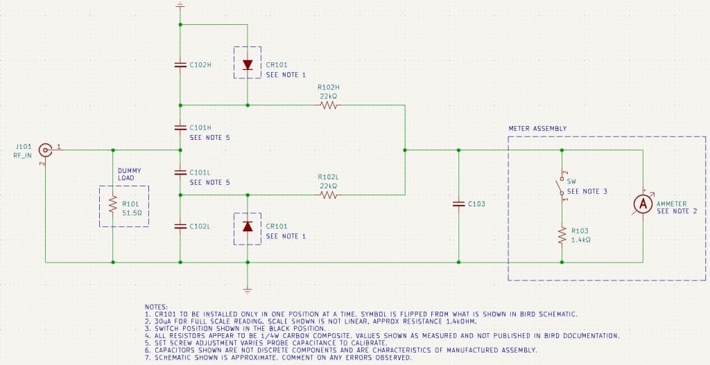
RF goes into the Type N J-101 port onto the equipment and a circuit is utilized for measuring the voltage across the dummy load resistor. The RF voltage sensing is performed by a the L(Low) side if the diode is placed into the X1 position or the H(High) side if the diode is placed into the X10 position.
C101 and C102 create a voltage divider, the RF signal is rectified via the crystal diode. C101 and C102 are likely configured with different capacitance values on the low vs. high sides.
The DC voltage section of the circuit includes R102 for dividing the voltage going into the current meter and C103 for filtering out AC components in the signal. A short piece of coax is used to connect the DC current to the meter assembly.
A switch is used to switch between the Black (low) or Red (high) scale. When switched to the Red (high) scale an additional 1.4kΩ resistor is placed in parallel with the meter.
The meter assembly on the 6154 ranges from 0-30 μA. Since power is measured as P=V2/R it should be noted that the scale values on the meter are not denoted linearly.
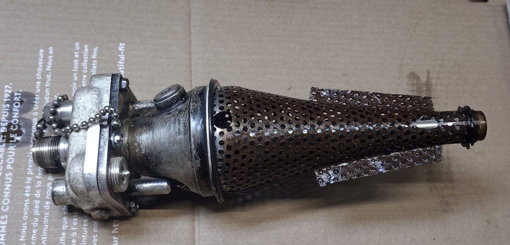
The dummy load itself is cone shaped, as Bird explains it on their website this shape was specifically chosen as it helps to create a frequency independent matched termination.
Resistor Element Link: https://birdrf.com/Blog/2019/June/RF-Thruline-Wattmeter.aspx
Tear down
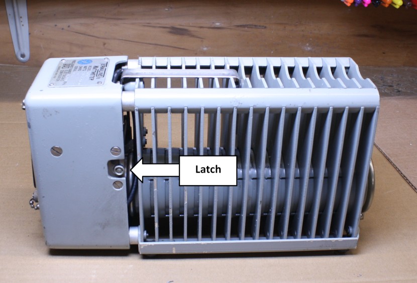
The meter can be removed by unclipping the latch that holds the meter to the dummy load assembly.
WARNING – The oil used in the dummy load likely contains Polychlorinated Biphenyls also known as PCBs. This material is a known carcinogen, if you choose to handle it, be sure to do research on its hazards and take the proper precautions. At a minimum wear non-pours gloves, do all work in a well ventilated area while wearing a respirator. If you need to dispose of waste oil be sure to coordinate with your local hazardous waste center for proper disposal. Many municipalities offer a house hold waste annually which will take similar hazardous materials.
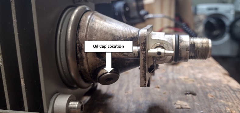
The oil can be inspected by removing the oil inspection/fill cap using an Allen head wrench. When removing the cap be sure to orientate the dummy load such that the oil will not spill out, I recommend having the dummy load positioned in a an oil catch pan to prevent accidental spills. The oil level should be up to the cap. For many dummy loads many folks replace the original oil with more readily available mineral oil (from a pharmacy), one down side to using mineral oil is sometimes you will get a bit of oil seepage. DO NOT replace the oil with common motor oil!.
From a curiosity stand point I decided to remove the resistive dummy load element. Under normal circumstances I would recommend against doing so as the oil can make a mess really quick. A picture of the element is shown below.
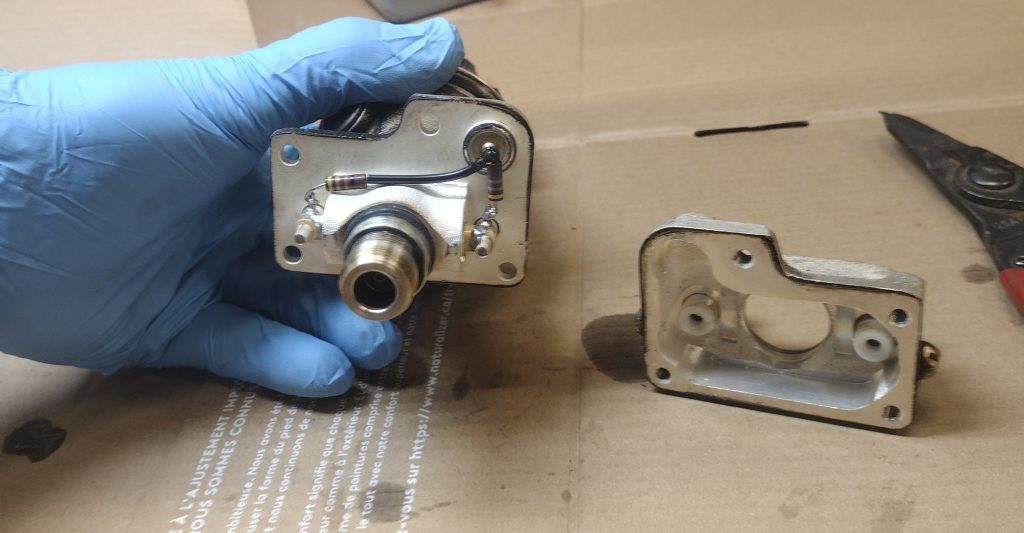
The cover over the R102 resistors can be easily removed by unfastening 4x screws located behind the cover.
Troubleshooting
There isn’t much to go wrong with the Termaline but inevitably anything that can go wrong will go wrong.
Dummy Load
When purchasing or troubleshooting one of these units the first thing I would suggest doing is connecting a digital multimeter between the RF connector center contact and shell. The measurement should be approximately 50Ω. Taking this measurement further would be to connect a VNA and perform a VSWR sweep. The measured value should easily be <1.5 from 0-1Ghz.
Meter Assembly and Cable
The meter assembly and cable can be exercised and tested for functionality using a voltage divider for feeding a current between 0-30µA.
For testing my meter assembly I used an adjustable power supply that ranged from 0-15VDC with a 325kΩ resistor inline with the current meter cable assembly as shown below.
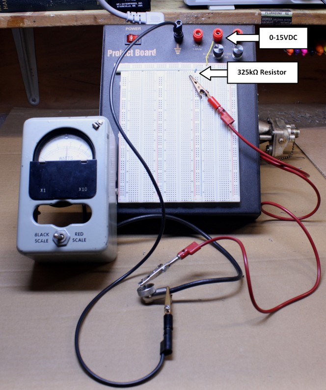
I start with the power supply at the 0VDC setting and gradually increase the voltage until I get a the needle to deflect. Using Ohms law V/R = I, we can determine the current flowing through the current meter by measuring the voltage drop across our inline resistor.
If you get no needle deflection I would suggest testing by connecting your leads directly to the meter and bypassing the cable assembly. If you get deflection of the meter then you know that your cable is suspect.
Crystal Diode Replacement
For one of the comparable military Termaline units Bird mentions that the crystal diode can be replaced in a pinch by filing away the spin over section of diode assembly to split open the metal case. This would be easier if you had a lathe. One challenge is that after you have accessed the diode there doesn’t seem to be an easy way to put the assembly back together.
Calibration and Level Adjustment
When I purchased my unit and tested it using a trusted radio in conjunction with a trusted watt meter I found that my Termaline reading was considerably off from what I was expecting. I tested the values of each of the resistors but found out that the unit simply needed to be recalibrated. To my disappointment the Bird manuals make no mention of any possible calibration procedure or adjustment.
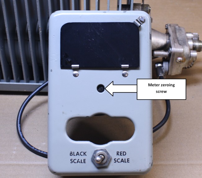
The first step is to ensure that when no transmission is present that the meter reads 0. If the meter does not read 0 then adjust the meter adjustment screw accordingly.
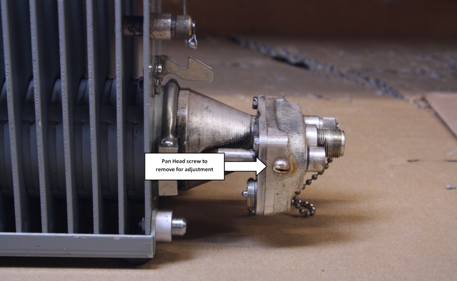
The unit is calibrated by adjusting a high and low side Allen head screws. As you tighten or loosen these screws you are adjusting the capacitance of the probes for both the low and high power sides. These Allen head screws are accessible by removing the flat head screws on the left and right side of the unit and as shown in the picture below. To calibrate the Termaline you need to have a transmitter and a highly accurate and calibrated in-line watt meter to use as a comparison.
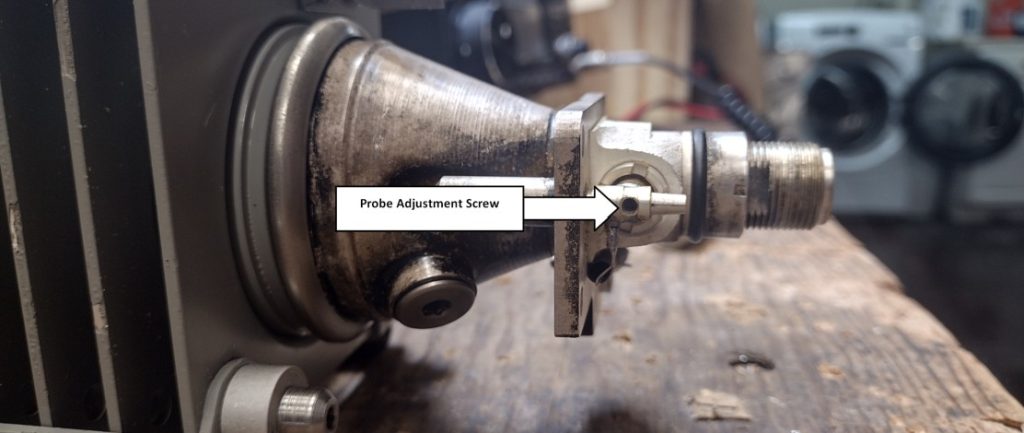
First adjust the low side. With the crystal diode plugged into the 1x port and the switch on the Black scale transmit using approximately 1W and adjust the Allen head adjustment screw to match the power reading from the in-line watt meter that you are using as your standard. Next perform this step for 5W or full scale. Switch to the Red scale and transmit using 15W, the meter should be read 15W. If required make some fine tune adjustments looking at both the 5W black scale reading and the red 15W scale reading to optimize the accuracy. Once the low side calibration is complete reinstall the pan head screw covering the Allen head adjustment screw.
Next adjust the high side. Move the crystal diode into the x10 port. With the switch in the Black scale transmit with approximately 10W and adjust the Allen head adjustment screw to roughly match the power reading from the in-line meter you are using as a standard. Next perform this step using 50W or full scale. Switch to the Red Scale and transmit using a 150W, again the meter should read 150W. If you don’t have a 150W transmitter you can use something with lower power. Again some fine tune adjustments may need to be made by comparing between the Black Scale and Red Scale. When completed re-install the pan head screw covering the Allen head adjustment screw.
If you have any additional information that I may have missed or noticed any inaccuracies feel free to reply to me with a comment below!